RMCA AR-8506-B
RECEIVER
Service Notes
The RCA Radiomarine (RMCA) AR-8506-B receiver is a wartime set made primarily to be fitted into the 4U transmitter console of a liberty ship radio room, together with an AR-8510 low frequency receiver. The manual, and a halfway decent scan of it at that, is available from the BAMA Manual Sever Mirror at
http://bama.edebris.com/manuals/radiomar/ar8506b
I have never seen an RCA AR-8506-A, but presumably one existed. The army procured a version of this set, labeled the R-203/SR, which, according to them, is "same as the civilian AR-8506-A."
There are several slight variations of this set. One has a separate on-off switch on the front panel in the form of a ball-tip toggle switch, while an apparently earlier design uses a switch on the volume control and has a plug button in the toggle switch hole. Postwar versions have dark gray panels with silk-screen painted labeling with a red RCA "meatball," while wartime sets have nameplates screwed to the panel. There were some models supplied in tabletop shock-mounted cabinets, while others were just the chassis, which slid into the slot for the HF receiver in the RCA 4U radio console on board ship.
There are plenty of photos of this receiver on the web, so I saw no point in adding more here. The purpose of this page is to offer ideas which will assist you in getting your receiver operational, not to act as a photo gallery or historical review of this receiver.
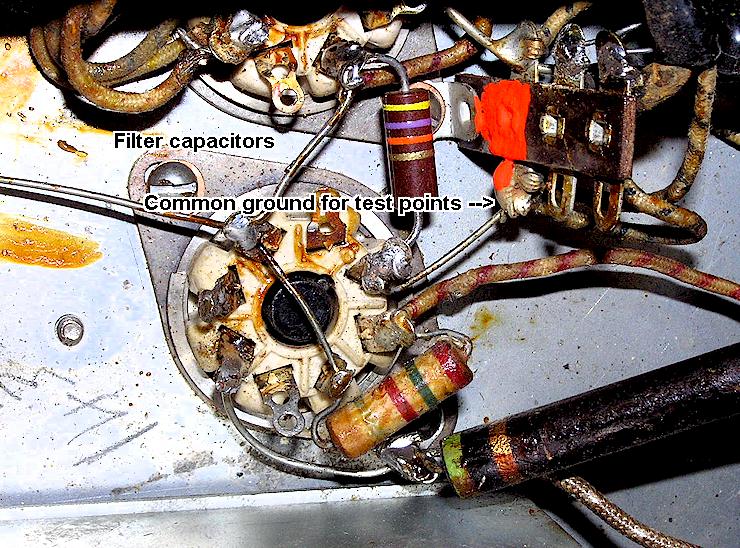
Power considerations: These sets are AC-DC and as such require some caution. This is not a "hot chassis" radio as some uninformed people often conclude whenever they hear the words AC-DC. The power circuitry inside, i.e. A-, is returned to a floating ground which is capacitively decoupled to the chassis itself, without direct DC connection. It is thus important to make sure that neither you nor previous owners have defeated this scheme by making ground connections to the chassis. It also means that servicing is best done with the set powered through an isolation transformer, and that the ground side of probes and measurement instruments can not be connected to the chassis. The ground side must be connected to the ground terminal of the power supply output, seen in the photo below and marked with orange paint. This point is identified in the schematic.
Bear in mind that the schematic and the way the receiver was originally wired, violates the color codes established by the present National Electrical Code. In other words, present NEC color schemes call for black to be the "hot" AC wire in household AC power wiring, and the white as the "ground" or "neutral" line. The 8506 is wired the opposite way, which can be confusing.
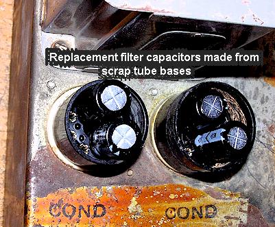
In my example, I found that the previous owner had replaced the filter capacitors with FP style can capacitors, wired to octal plugs, but with the ground sides tied to the chassis at the socket pins! This is wrong, as FP style multi-section capacitors return the grounds to a central point (the can) and can not be used. You must use individual capacitors with the (-) sides independent of one another. I used a pair of 47 mfd 250V radial lead electrolytic types obtained from the TV repair parts house, built into the octal base of a scrap tube. At the time this is written, February 2009, a good source for inexpensive high voltage electrolytic capacitors (as well as a wide selection of semiconductors) is Match-a-Knob Electronics in New York. They have a shopping-cart style website and this makes ordering by credit card fairly easy.
Line Filtering: Originally the AR-8506 was connected to the matching RM-8 line filter unit. These are out there; I was able to buy one on eBay for $ 8 with no competition. Presuming you cannot find one, you can make one using a surplus AC line filter such as those by Corcom or Tobe. You will need one capable of at least one Amp. It may not be necessary to use the line filter at all; it was intended for shipboard use where there can be a great amount of electrical noise on the power mains from generators and the like. I used it because I had it.
Line Cord: The line cord originally connected to the receiver via a two prong "Twist-Lok" connector, the male half of course being the chassis side. These are still available if you look hard enough; also check under the tables at electronics flea markets and that sort of thing. It is recommended that whether you use the accessory RM-8 line filter or a home made version, or none at all, that you ground the cabinet of the AR-8506-B to a good earth ground, or at least the ground prong of a three-prong all socket. The manual makes the rather confusing statement that it is possible to receive a shock "from the capacitors charging" if the set is not grounded. I am not sure what that is about; the current leakage paths in this sort of set are a bit confusing and it's best to avoid the whole issue by grounding.
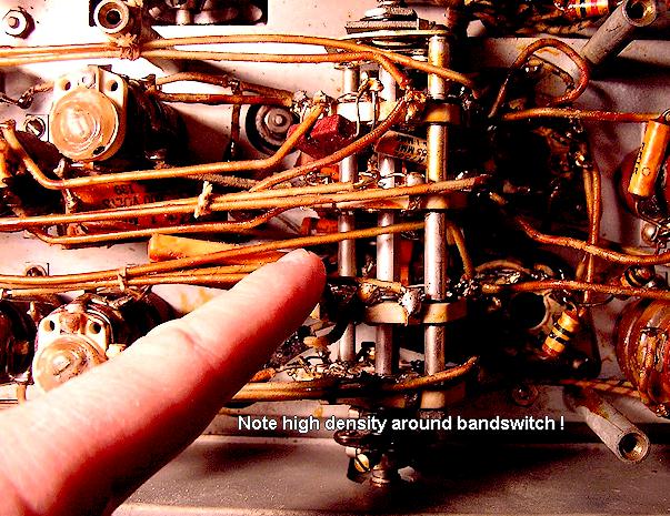
Basic Overhaul: It is unlikely that any of the wax-paper tubular capacitors in these sets are still good, and they will all have to be changed, although some of them with low voltages on them could be left alone. Make sure to replace them with the same or closest modern values. It helps to have a solder-sucking squeeze-bulb and a doctor's hemostat when removing these. Check the resistors for any which have gone high (it is not necessary to unhook one lead of the resistors to measure them.) If the original electrolytic filter capacitors are still there, check them for leakage with a tester such as the Eico 950 or a Sprague Tel-Ohm-Mic, and preferably for ESR with an ESR meter such as the Dick Smith type. The tubular electrolytic located under the filter choke and output transformer area will usually (always?) be defective. In my example, the "Candohm" metal clad wirewound resistor across the rear apron, which acts as a filament dropping resistor, was intermittent if not completely open, which is a common fault with that style.
Note the component density in the photo below; these wax tubular capacitors are some of the hardest to reach!
Neon Lamp Issues: The neon voltage regulator bulb is also used as a panel lamp. The manual doesn't identify it by type number, but it is an NE-32 and is not easy to find. It has a large round globe and looks like a flashbulb. The 991 type regular bulb, as used in early BC-348 receivers, will also fit, however I believe it is incapable of the current requirements met by the NE-32, and it also will not properly act as a pilot lamp due to the smaller physical size of the bulb and interior elements. You can substitute a 60-70V Zener diode if this bulb is missing, but you will need to adjust and select the value of a series current limiting resistor if you do so, and make some other arrangement for a pilot lamp.
In my receiver, the neon lamp would not insert fully enough to engage the bayonet slots and turn to lock. This turned out to be because there are two stiff pieces of wire exiting the bulb's socket base, used as tie points for the regular flexible wiring from the harness. These wire stubs are held in place by setscrews going sideways into the black fiber section of the socket. The wires were inserted too far into the socket, preventing the spring-loaded contact pins from fully retracting when the bulb was inserted. Loosening the setscrews and pulling the stiff wires out somewhat, solved the problem. It is necessary to remove the socket in order to access the setscrews.
Hardware: The screws on the front panel are an unusual thread; 4-36. 4-36 screws are still available from some vendors, you'll need to do a Google© search to find who has them at any given time. The nameplates can use 4-36 x 1/8 while the plastic dial lens probably will probably require 4-36 x 1/4 or 4-36 x 3/16. The 4-36 screws are an odd thread so you may have to use what you find and cut longer ones down. Cut down because the chassis is not bored behind the panel screw holes, and some of the screws, if they extend through the panel, will hit the chassis and bind.
The screws in this set, regardless of location, should all be slotted head style. Phillips-head screws only became popular during the war and were not used in the AR-8506 sets. The screws holding the RF section covers are a more standard 8-32 pan-head slotted type.
Unusual Faults: My receiver failed to function after the labor-intensive replacement of all wax and electrolytic capacitors, along with many other parts. This turned out to be caused mainly by a shorted trimmer capacitor in the last IF can before the detector, see photo below. The collar holding the rotor shaft had allowed it to slip downward from spring tension, and short the plates. This can usually be found by trying to turn the trimmer shaft, in which case the shaft will either be jammed or the feel and sound of plates hitting one another will be present. It may be possible to simply press the existing collar back onto the shaft by using a pair of Vise-Grip® pliers which you adjust to slowly tighten and lock each time, pressing the collar on one end and the shaft bottom on the other, until the plates are realigned. In my case, the collar fell completely off when I removed the aluminum IF transformer "can," and disappeared somewhere on the floor, so I cannibalized another collar from a scrap "Sickles" brand trimmer capacitor and used that. I drove the collar off the shaft of the scrap capacitor with a pin-punch and small hammer, and pressed it onto the original trimmer shaft using the Vise Grip method mentioned above. After repairing this, the receiver still didn't work, but only because the previous owner, in an apparently desperate attempt to make the poor thing function, had turned all the IF transformer trimmers far out of alignment. Below is a photo of the trimmer problem:
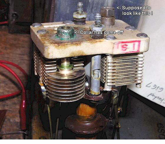
Note that the trimmer screws have voltage on them, so use an insulated tool when aligning and don't the tip make contact between trimmer screw and can.
Beware rotten rubber shielded cables which take the detector output to the volume control, and then back to the 1st audio amplifier and AVC tube. Internal shorts can cause reduced or distorted audio.
IF Interference: Depending upon where you live, you may find the receiver unusable, especially after dark, due to strong IF frequency interference from broadcast stations. The IF frequency of the AR-8506 is 1700 KHz. Since the early 1990's, the "new" expanded AM broadcast band has resulted in stations appearing all the way up to 1690 KHz, creating interference for receivers using IF frequencies in this range, such as the Hallicrafters SX-101 (1650 KHz IF.) So, why should this be a problem for the AR-8506, which has a 1700 KHz IF? Because there is at least one station outside the USA, broadcasting on 1700 KHz, namely "San Diego Talk Radio 1700," located across the border in Mexico. My bench measurements show that a signal at the antenna terminals of the AR-8506 of as little as 300 microvolts will completely swamp the IF of the set and render band 3 totally useless (as well as the upper bands, to a lesser extent.) I was unable to get the wavetrap capable of attenuating the IF frequency at the antenna terminals by greater than 2-3 db. I am still experimenting with what to do about this, but so far the traditional and simplest solution of moving the receiver's IF frequency up a bit seems to have cured it. I tried 1712 KHz, which may be more than necessary, although I felt this would positively eliminate any heterodynes from IF interference. I have not been able to get Band 3 to correctly track on the dial scale, even with the IF at its intended frequency of 1700, so I can not report on whether there are any tracking problems associated with moving the IF slightly to avoid interference. The better solution is probably to build a multi section high- pass filter to be inserted into the antenna input.
Defective ceramic trimmers: The RF deck uses 15 ceramic trimmers on the various coils, and all are NPO type, 3-12 pf. They sometimes seize and break, especially if someone has poured wax or glue on them. These are getting hard to find from surplus sources; at the time of this writing, surplus dealer Electronic Goldmine in Arizona has unused exact replacements for $ 1 each, which is a steal as these things go.
Service manual inadequacies: You will find that the manual is well below the standards expected of something intended to assist servicing a communications receiver. There is no tube socket layout guide which identifies the tubes and their functions from underneath the chassis, nor is there a tube pin voltage chart (although most voltage measurements are found in the schematic.) To solve this, I have drawn up some pages which you should download and print, and use as a supplement to the service manual. Also, I have scanned and included a few faded mimeo sheets found in my original 1943 dated manual, from the Radiomarine Engineering Department, consisting of alignment instructions and an interesting laboratory test sheet used as a final test record on the production line. These are all Adobe PDF® documents. Click on any of these below:
AR-8506-B Under Chassis Layout
AR-8506-B IF-RF Alignment Points, Top View
AR-8506-B IF-RF Alignment Points, Under chassis View
AR-8506-B Tube Socket Voltage Measurements
AR-8506-B Radiomarine Engineering Dept. Alignment Notes (2 pgs.)
AR-8506-B Radiomarine Engineering Dept. Lab Test Report Form
Questions, comments, suggestions? Contact me --> geoff @wb6nvh.com
Ver.3/05/2009