AEROTRON
Synthesized MEGA
LOW BAND MOBILE RADIO
I recently acquired some Aerotron APC9RB70SM100D low band high power mobiles which are surplus from the North Carolina Highway Patrol and as there was nothing on the web about it, I decided to publish the following information.
The standard Synthesized Mega radio is a 1981 vintage 16 channel system which was sold in several frequency ranges. It is programmable. Depending upon the model, this is accomplished either by cutting leads on a diode module arrangement or programming an EPROM chip.
The original "standard" control head was a clamshell affair resembling a Motorola Micor control head, with a rotary channel selector.
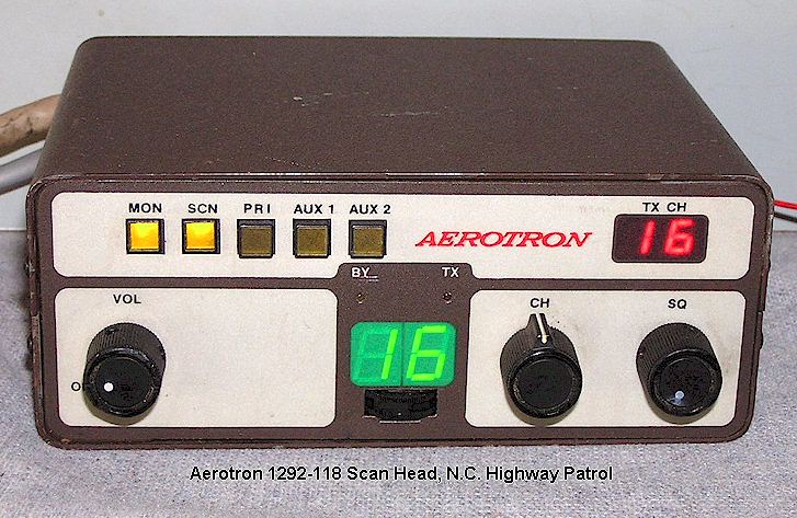
The NC Highway Patrol equipment was used with a 16 channel scanning control head as shown below. This head is Part No. 1292-118. The control functions are straightforward, except perhaps for the AUX 1 and AUX 2 buttons. These can be wired as needed, but most have one as the auxiliary speaker and the other turns the noise blanker on and off. Unfortunately the basic Public Safety head as shown below does not have a way to lock stations out of the scan list, although you could make a small switch box to do this, which is how Aerotron did it, with a separate switchbox mounted below the main head. The channel indicator LED displays are interesting and allow easy recognition of the channel your transmitter is set to and which channel the scan has stopped on.
To some extent you have to be interested in something different to want one of these, because a Motorola Syntor X mobile which will cover both 10 and 6 Meter amateur bands has fallen in price so much that it isn't particularly worthwhile to buy one of the Aerotron sets unless it's very cheap.
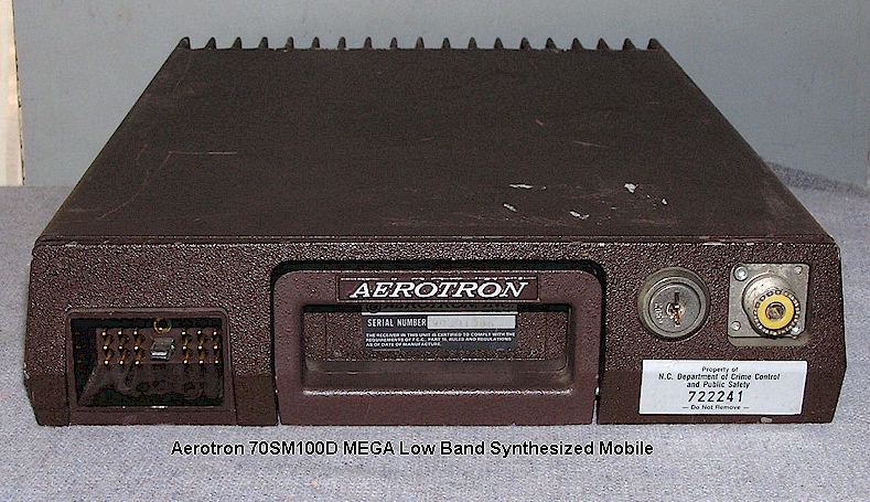
A typical "D" Series radio assembly is shown below. The main connector appears to be proprietary and the radio drawer size is approximately that of the Motorola's original Syntor radio.
TECHNICAL DETAILS:
The Bandwidth Bugaboo
Unlike the Motorola Syntor X or GE Rangr equipment, these are not broad banded radios! You get about 3 MHz without retuning. If you are only using the radio on the 6 Meter ham band, this won't matter to you. But if you want to monitor some 42-50 MHz channels such as state police or business, it is not happening, or at least not well. And this also means that unlike other brand radios where you can program and have it ready to go, you will have to do an RF alignment when moving it to 6 Meters.
The "D" Series:
There are two models of Mega low band mobile you are likely to come across. One is the original "D" model, as shown above, which is in a pebbly brown colored drawer assembly and which uses a diode-matrix programming scheme on a board hidden inside the VCO box assembly. There are 16 diode modules for the receiver and 16 for the transmitter. Programming consists of clipping certain diodes in each module, by following a chart in the manual or using the formula. It seems that the only major sale of these was to the North Carolina Highway Patrol and related N.C. agencies. The "E," described below, seems to have been sold in any quantity only to the State of Texas Highways Dept. for use on 47 MHz channels.
The "E" Series:
The "E" model appears to be essentially the same as the "D" except that it uses a 2758 EPROM chip instead of the rather ridiculous forest of diodes found in the "D" model, and is in a black painted drawer assembly with a sheet metal top lid instead of the thicker cast lid of its predecessor. The "E" model has an almost empty circuit board in the VCO compartment top deck, containing only the socketed EPROM. The control cable for the "E" uses a black colored connector housing but otherwise appears the same as the "D" series. The EPROM board assembly can be retrofitted into a "D" model Mega. The black "E" models would seem to be preferable provided you have an EPROM burner, otherwise you are better off with the "D" models. But be aware that someone may have substituted VCO boards! The manual for the "E" series should be available as a download from the Repeater-Builder website. Within the manual is a chart set and assorted formulae for programming an EPROM to use with this equipment from scratch if you have an EPROM burner such as a Data I/O System 29B although the process of doing so manually ios rather mind-numbing in this day and age. Note that this chart is different from the one in the ":D" manual. The "E" manual also states that software was available from Aerotron "for the IBM PC" to create EPROM channel lists and for programming the 2758 chip. Which must have been DOS based. But that was then and this is now! If you have this software, please share it and I will see that it is put to good use by those who find this page.
The Keys:
All Aerotron equipment to my knowledge uses the same Chicago double-sided key, pattern no. 2059. You can get a key occasionally on eBay or there is a company on the web that makes Chicago keys to order by pattern number.
The Trays:
I don't know why, but for some reason the mounting trays are always missing from these drawers. Presumably they are orbiting some far planet in a galaxy far away along with all the cabinets for Hammarlund Super Pro SP-600's, the covers from R-390A receivers, the watches from Wireless Set No. 19's, BC-348 dynamotors, 1L6 tubes, Freon 12 and leaded Supreme gasoline. Stay tuned for the results of my attempt to manufacture a tray. A belated thank-you to those far-sighted Motorola design engineers of the 1950's and 60's who made the bottom half of the cabinet the mounting tray on their equipment, and a pox on the designers who thought up the stupid idea of a separate tray, so that lazy morons who uninstall radio gear could just leave it in the surplus vehicle. I need at least one tray (can copy it to make others) so if you have a spare one, let me know!
6 Meter Conversions:
Please note that because of the Mega synthesizer scheme, there is the selection of 20 or 25 KHz channel spacing by a jumper, so that only one or the other can be used. Unfortunately, 52.525 MHz, the national 6 Meter simplex channel, requires using the 25 KHz spacing jumper instead of the 20 KHz jumper. As a result, if you want any other channels besides 52.525 (as most of us do,) and those channels won't divide by 25, they can't be programmed if the radio is set up to provide 52.525 ! One solution to this appears to be to place 52.525 in channel 1, and all other channels in positions 2-16. Then a small circuit is built up to sense when the channel select line is at position 1, and this then toggles the 20/25 KHz jumper open or closed accordingly, using a transistor switch.
The receivers are rather nice in these radios. They should tune up to at least 53 MHz without modification, but be aware that the tuning of the noise blanker can affect this and a receiver with poor sensitivity may be this way because the noise blanker is set too close to the channel frequency. Also note that the manual states these sets have only a 3 MHz bandwidth, so tuning to the amateur band will require an RF re-alignment.
PROBLEMS:
I have found bad solder joints on the boards closest to the front panel at the power entry area. Other problems and solutions will be added here as they are discovered. Write me if you want to add anything.
MANUALS:
Thanks to Jim Gatlin, N4YB, I now have a pdf copy of the manual for the 1292 control head. Send me a note if you need a copy! The main "E" manual should be available on the repeater-builder website, including the diode matrix or programmer settings for 6 Meters as well as the original ranges, thanks to Jerry Coffman.
Geoff Fors, WB6NVH Monterey California Contact me: geoff@ wb6nvh.com
Ver. 2/20/2024 Copyright Geoffrey C. Fors, 2010