GE S820 SERIES
CONTROL HEAD PROGRAMMING TUTORIAL
This page is designed to assist first-time users in successfully using the General Electric factory programming software for the S820 and S825 series of control heads, using the TQ-3370 or equivalent interface box (such as a Polaris.). At this time it is written with reference to Version 3.0 of the S825 programming software although Version 4 appears to be nearly identical.
Please note that I run a busy small business alone and get a lot of E-mail related to my web pages. Unfortunately I just don't have time to answer E-mails regarding personalized help teaching this software or diagnosing issues that you can solve by reading the information below. If you still need help after reading this page, it is suggested that you join the Groups.io GE Delta-Ranger Group or one of the other GE groups and post questions there.
This information is not applicable to the TQ2310 "Suitcase Programmer," an older and completely different item. While primarily written for those using the TQ3370 interface box, it appears that the TQ3330 interface box (Delta-Rangr) will also program the S800 series control heads provided the proper cable is used.
"CHP" Heads: Please note that the California Highway Patrol Series S810 (Car) and S815 (Motorcycle) control heads are special 128 channel ("64 Mode") products which have different firmware than "stock" GE heads, and are also older. They are still in use, although the CHP is in the process of retiring them (as of 2011.) Thus you should not find any "legal" CHP heads on the open market for some years. It is impossible to correctly program CHP heads using the normal GE "S825" software as they are totally different. The CHP head has no "Channel" button and does not store the channel information in "banks" of 16 channels as in the standard heads. Instead, the "Mode" button steps entirely through 64 channel sets (2 channels each) with a "talk around" setting for each channel ("C".) This is somewhat confusing as the standard S-825 heads use "Mode" to denote a channel bank, rather than a specific channel. Further, the CHP head programs via the J3 Molex connector pin set and the microphone socket on the back via either the TQ3330 or TQ3370 RIB unit, modified, with a cable assembly you will have to mock up from scratch ( Unlike the standard S820 or S825, or via the older suitcase programmer.) In addition, the CHP heads use a different Molex connector for the power connection (J1,) a single row style as used on the Phoenix series of dash mount radios (but with different wiring.)
BASIC SPECIFICATIONS
The S825 series control heads technically allow a maximum of 256 channels, consisting of 16 channels per bank, in 16 banks called MODES, although it is possible to add more channels until you run out of memory space (watch the "Bytes Remaining" message on the lower right corner of the screen.) I am not sure what happens after the 16th channel in each "mode" when connected to a radio with only a single X2212 EEPROM chip, which is technically limited to a maximum download of 16 channels. Presumably you would also need to add the second X2212 EEPROM to the radio and add the jumper/s to make a 32 channel radio. The term "Mode" is confusing if you are used to Motorola Syntor X9000 equipment, where "Mode" basically refers to a channel.
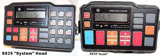
The front panel pushbutton labeled "MODE" briefly changes the channel select button to a mode select button when it is depressed. The MODE button does not itself select any modes, it just toggles the two functions of the channel select key. This is not at all obvious without a study of the manual! There are two models of these heads: SCAN and SYSTEM. SCAN has fewer pushbuttons and was typically employed on motorcycles or in cars which did not have sirens and lights, or where it was desired to retain a separate siren/PA/lighting control box. SYSTEM has an extra set of smaller pushbuttons on the right hand side, to control sirens, lights, and various other features as the programmer selects, and those buttons can apparently be configured as a DTMF pad with the later ( V. 4) software.
The SYSTEM control head communicates with the siren/lighting system over a serial communication cable. Originally, this feature was intended for use with a "GE" model of the Federal Signal SS2000 siren/light box but since then a number of other types have been developed by both Federal and their competitors. The cable from the S825 series control head normally terminates in a DB-9 male plug at the siren/light control box end, and uses the same set of pins the programming cable does.
On both versions of control head, most of the buttons are programmable as to their function, but this is essentially useless on the "scan" type heads. The software will provide you with a list of possible functions which you can assign to these buttons. It is important that you only assign a specific function to one button, because the program does not allow more than one button to activate the same feature or have the same name. I suggest you avoid reprogramming any of the buttons other than the ones for the assorted switches on the right hand side of SYSTEM version heads, or the "AUX" button on the S820 series. Reprogramming the buttons to do functions other than the default choices can get very confusing!
You can find many of the manuals and assorted documentation on these heads at the GE Files section of the Repeater-Builder website. [2024 Update-->] The programming software, both versions, was once available in the Files section of the Yahoo "GE" group, but Yahoo dropped all groups some years ago. It may be available elsewhere on the web, and unlike Motorola, there is no big deal about sharing it. Bear in mind that you will have to "fix" the software after downloading and unzipping it in order to get the "help" files to work. See the instructions below.
S800 Head Version Summary
This is a summary of some of the more popular head configuration numbers:
S810 : CHP Only, Special, Original "System" Control Head
S815 : CHP Only, Special, Motorcycle "Scan" Head
S820: "Scan" Head, Standard
S825: "System" Head, Standard
S830: Later numbering system, can mean System or Motorcycle Scan head
S850: EDACS Trunking (non conventional) Head (basically useless)
There are also some later numbers that look something like this: "S825025," in which case, just refer to the first three digits after the "S."
PROGRAMMING EQUIPMENT REQUIRED
1) A DOS based computer with a serial port, such as a 386 based NEC, Compaq, Packard Bell, etc. laptop would be ideal. You may or may not be successful using recent Windows machines running in DOS mode. This GE software is DOS based, not Windows based. If you find it necessary to go shopping for one of the older machines, please note that the hard drives used in the oldest "boat anchor" PC's were usually "Winchester" or proprietary type RLL and MFM interface drives which were rather unreliable and many if not most of them will be defective by now, particularly in laptops and portables. Hence the number of dishonest sellers on eBay claiming "unable to test" or "as-is" regarding such machines. Replacement Winchester and MFM laptop hard drives are very hard to find, nonexistent in new condition, and usually outrageously expensive when found. A working hard drive should be made a condition of purchase. One option, somewhat less convenient but more reliable, is to use an old desktop 386 style PC which uses a standard IDE style hard drive. I haven't tested the limits of this software, or versions other than 3.0. A newer PC may work fine, although be aware that much "RSS" software from this era, particularly Motorola, crashes if run on a computer much newer than a 386. Please also remember that a Windows type machine running in the "DOS" window mode is not the same as a machine running true DOS, and that many new PC's have eliminated the conventional serial port altogether!
The GE software was written for use with a color monitor but it will work on a monochrome type, with some annoyances regarding the contrast control. This is a problem with laptop type computers because few if any of the older DOS laptops had color screens. It might be easier to compose the files on a desktop PC with a color monitor and then transfer the completed products to the laptop. Makes you wonder what they were thinking when they wrote this software.
2) GE "RIB" Box TQ-3370. This is a serial interface level converter from your computer to the control head. It is possible to build one, there are schematics on the web and in the files section of the GE Group at Yahoo. Aftermarket manufacturers such as Polaris, Niles and Price Industries also made them, but make sure if you get one of those that it supports the GE RIB function rather than the more common Motorola RIB. The GE RIB is not the same as the Motorola. The original GE boxes occasionally show up on eBay. Apparently the TQ3330 RIB box will also work, but I am not sure whether the cable is the same. Substitute TQ-3330 for TQ-3370 throughout this page where necessary if that's what you have.
3) Programming Cables. You will need a standard serial cable from the computer to the TQ-3370, and a special control head programming cable from the TQ-3370 to the control head. The cable from the "RIB" box to the radio is terminated at the radio end in a special 26-pin AMP Corp. plug, type number: 2-87456-2, the pins for which are numbered 87523-6 or 1-87523-6 or 1-87523-9. Both are available from Digi-Key or Allied Electronics. The programming cable diagram is on the Hall Electronics GE Tech website (Click here) . This cable connects to the set of pins on the rear of the head which are normally used by the siren-lamps-accessory cable when installed, i.e. J5. You can also buy a ready-made cable from Price Industries, and sometimes on eBay. Further, RF Guys sells a "ribless" cable which has the level converter built-in, so that you will not need a RIB box at all. They regularly sell on eBay and you can probably track them down on Google. But...you will still need an old DOS PC to run the software, and you will still need a serial port on the PC!
4) The control head software. This was once fairly easy to find on the web, but not so much anymore. It may be available in the files section of the Groups.io GE Rangr-Delta Group. This web page was written for Version 3.0 but most everything should apply to Version 4.0 as well. I have not sorted out the differences yet. The software is referred to as "S825." There was no Windows version of this software.
SOFTWARE BUGS AND MISCELLANEOUS NOTES
Unzip Error: The software which is occasionally available on the web or from hams is in "zip file" form and there is a bug when it is unzipped. Namely that the help files will not work when the package is unzipped in a normal fashion. This is because the package unzips the help files to the same directory as the program files, and the program cannot find them in the directory it expects. In that regard, it will be necessary to do one of two things; either unzip the entire program twice, each into a separate directory, by way of example one being C: \ S825 and the other being C: \ S825 \ HELP, or, move all the files ending with the extension .hlp into the C: \ S825 \ HELP directory. For example, to start, at the DOS prompt enter MKDIR S825. Then unzip the S825 programming files to the C: \S825 directory. Then , while in the S825 directory (the cursor prompt should say C: \S825> ) enter MOVE *.HLP C: \S825\HELP. Read up on DOS file transfer commands if you aren't familiar with how to do this. Version 4 of the S825 software contains an "install" command file but I have not been able to get it to work yet, as it produces an "error" box saying something about "necessary files are on Disk 1" and then fails. Instead, I have just unzipped and manually placed the two software folders, which will give you the same issue mentioned above with the HELP files until you move them. All of this presumes you have an unzip utility program in the first place to unzip the files. Contact me if you need help with this.
Out of Band Channels: Amateur range channels will trigger an error message if you attempt to enter them. This is solved by over-riding the range lockout in the program, by pressing the "INSERT" key or "CONTROL and E" rather than the "ENTER" key for these frequencies. Please remember that the radio itself will require VCO and in some cases filter modifications to function on amateur channels (e.g. 6 Meter radios.) Please also note that there are at least two web pages with erroneous information regarding 6 meter ham conversions of the RANGR radio. These sites claim that the only modification necessary is to the VCO, which is incorrect. The transmitter low pass filter must be modified to move the beginning of filtering up to 54 MHz, otherwise a substantial amount of power begins to be diverted in that filter above 50.5 MHz, and overheating failure of the power amplifier transistors is inevitable. "Control-E" will only allow you to enter channels a maximum of 10 MHz outside the operating range of the radio you chose when creating the file. In other words, a 450-470 MHz radio can be programmed with amateur 440 MHz frequencies (after resetting the VCO,) but forget about some 439 MHz channels!
Interface box: Note that it is not necessary or desirable to have the interface box attached to the control head while creating the program. The interface box and cables are only used when the control head is actually being programmed.
"Dual" display: Many flea market and eBay control heads may arrive displaying only the word "DUAL" when powered up, with no action from the control buttons possible. These are usually S820 heads from GE DELTA installations in ambulances which had rear compartment secondary control heads, and to use them that way, you need a dual head adapter box. Presuming you don't want to do this, and would like to use the head as a conventional item, don't worry. When you download your program into the head, this can be removed. The "Dual" option is selected or de-selected during programming by using the F5 key from the appropriate screen.
Radio Setup: There are jumpers in the radio drawer itself which must be set to allow use with a "downloading" control head such as this series. The number and placement of the jumpers depends upon the band, series and model of the radio drawer, so refer to the manual for that radio to insure that the jumpers are located in the correct positions. The radio jumper or jumpers should be set to "allow downloading." There are also jumpers on the head itself which determine whether the audio feedback "beeps" on key press will occur. Consult the appropriate manuals.
Noisy backlighting: The power supply for the "back light" which illuminates the LCD display is acoustically noisy and emits a high pitched whine which may be audible in quiet conditions with the vehicle engine off. Depending upon the brightness setting, this noise varies in pitch. This is normal and unavoidable. It should also be realized that nearly all S800 series control heads are now 15-18 years old. The electro-luminescent back-lights have a finite lifespan and quite a few of these control heads have dim lighting even with the brightness set to maximum. This is why the software allows for a "light saver" mode which shuts off the back light circuit in daylight, via a photocell sensor. This can be confusing on the workbench because unless the room lighting is shut off, or the photocell covered, the control head will not illuminate. There is a mode in software which allows a complete shutoff of the backlight if desired, as opposed to a minimum brightness setting. This is for "undercover" use where it is desired to show no lighting inside a vehicle. It also has the annoying disadvantage for us that it turns off the LED's for the transmit, busy and scan functions!
Fragmented LCD Display: Fragmented or distorted numbers and characters on the LCD display are usually caused by a dirty, poorly aligned or loose "zebra strip" which is the conductive rubber strip sandwiched between the LCD glass and the display board. The older versions of the display board come apart easily with screw fasteners and the LCD panel is held in by a clear plastic frame which pops out easily. Newer heads have the LCD assembly held in by bent tabs of the metal frame surrounding it and are a real pain to disassemble, however they are apparently more reliable. In either case, it is necessary to delicately disassemble the glass LCD assembly from the board and zebra strip, and clean the glass, zebra strip and board contacts with a lint-free object (not a q-tip!) soaked in residue-free contact cleaner such as QD Electro-Clean solvent or perhaps denatured alcohol. Cleaning and rejuvenating the LCD displays is not always a completely successful effort, unfortunately. LCD displays do not last forever, but in most cases poor contacts seem to be the fault rather than defective LCD panels...
Blown Traces: The boards in these control heads contain very fine traces, including those for the power rails, which in my opinion are too tiny for this application and certainly not enough to carry current. Additionally, there are no small "picofuses" on the rearmost board to protect the head from reversed polarity, shorts and the like. As a result, it's common to find heads with burned-open and/or popped-loose foil traces throughout the rearmost board. The solution to this is to repair the traces, usually with small gauge solid enameled copper wire, using insulating sleeving where necessary. In some cases components may be damaged as well, and in that situation, due to the surface-mount nature of many parts, it's probably simplest to discard the board and seek another from a "parts" head.
"Flash Programming": Flash programming is not the same as the regular programming routine (which is used for channels and alpha-numeric display names.) Flash programming will change the overall firmware in the control head to allow different features and so forth, none of which would be available by using the normal software. Flash programming can be performed only with the TQ3370 interface box, however the cable to the head is different; it connects to the mike jack instead, and the "flash" software is also different. I am unaware of any conventional flash software, or its capabilities. Information on this is solicited! It is not necessary to have or understand the flash software to successfully program these control heads in a normal manner. Also, the older versions of these heads do not have flash capable memory chips, and can not be flash programmed anyway.
Radio cables, "G1 and G3": There are a couple dozen cables which connect the radio to this style control head. You will need a "downloading" cable, which in the earliest series of cables usually had a part number ending in G1. The cables with numbers ending in G3 were not wired for downloading, however they could be easily modified to do so because the wires are there, just not connected. Check Google for web pages with this information. There are cables which end in many numbers other than G1 or G3. Most are already suitable for downloading. See the list of applicable cables at Hall Electronics' website, but note that some numbers on that chart appear to be incorrect, e.g. some of the numbers identified as "short" cables for bench use are in fact not, but rather "long" cables for fire engine and ambulance applications. [2024 Note-->] In August 2024 it was not9ced that the Hall Electronics' website had become corrupted with much of the "GE Tech" files being missing and coming up 404. This resource may be disappearing and it may be prudent to print or download screen shots of data you want before it disappears completely.
EDACS Heads: There are many of these control heads on the surplus market from EDACS systems. EDACS is a proprietary analog trunking system developed by GE, and not a conventional radio. The majority of EDACS systems are found on 800 MHz although the military seems to have employed a few large scale EDACS systems in the 403-416 MHz range somewhere in the United States, in foreign countries, and on ships. EDACS heads require different software and will not control a conventional radio. The EDACS software is loaded into the radio, not the head, unlike the conventional S820 and S825. Apparently it is possible to program a few conventional channels into an EDACS radio, but you must use EDACS software and the EDACS programming cable, both of which are totally different from the topic of this web page. Without the matching radio and cable, the EDACS heads are basically worthless other than for parts salvage. You can recognize an EDACS head because one of the larger buttons will be marked "GROUP" and the keypad colors are slightly different. There is also an equally useless "Eurodacs" head made for foreign markets. It is not known how different those are from USA EDACS heads.
HOW TO CREATE THE FILES AND RUN THE PROGRAM
The first step is to install the software in your computer. If you obtained it over the web, it was probably in the form of a zip file. Zip files today are a nuisance which date back to the days when the biggest portable storage medium was a floppy disk and everyone was using 28.8 kb (or slower) dial-up internet connections. These files must be unzipped with a utility such as WinZip. I suggest you create a sub-directory in DOS and unzip the GE file to that, so that it doesn't become confusing later, as there are quite a few files in it. For example, when you are finished, a typical subdirectory would be S825, and when you want to use this file, you would enter the DOS command CHDIR S825 [enter] at the C:\ prompt and that will then take you to the correct directory, where you then start up the software with the command S825 [enter]. Alternatively, if you are conversant with DOS programming, you could write a batch file which would do everything for you from a simple one-word command. See the comments above regarding the "unzip" bug in this software.
The software is anything but easy to use, especially if you are not using it on a daily basis. The main purpose of this web page is to help you get the program running in a minimum amount of time. Unlike Windows and most DOS programs, the ENTER key isn't used in the same way as you might expect. The program expects you to use assorted Function ("F1," "F5," etc.) keys rather than the ENTER key for many commands, and the F10 key instead of the ESCAPE key to leave a particular screen.
INITIAL STEPS:
The initial "home page" screen should be the "Current Personalities" screen. It shows personalities previously created. If you haven't created any personalities yet, then obviously there will be none shown. You can not create a personality without the frequency sets being created first. Thus you must first press the F1 (SETUP) key, and depending which version control head you have, you may have to press the F3 (KEYPAD) key until the correct control head button layout appears in the left window. After that, press the F1 (SWITCH) key to change the cursor to the right hand window and use the F4 (RANGE) key to pick which type of radio is being controlled by the head. The ENTER key steps the cursor through the various frequency ranges. Please note that if you have adjusted the VCO to allow operation on an out-of-range channel (i.e. ham bands) you should still use the range the radio was manufactured for originally. If you have converted the VCO to be equivalent to the VCO for a different range radio, then use the range appropriate to the VCO as converted. Watch out for this on the UHF Rangr radios, where it is tempting to select the 430-450 MHz range when programming ham channels, while the radio is really a 450-470 range unit with the VCO adjusted downward. Make sure you have selected which radio you have, e.g. Delta or RANGR.
PERSONALITY SCREEN:
Following the above steps, press the F10 (BACK) key and return to the "PERSONALITY" screen.
CREATING FREQUENCY SETS:
Anytime it is desired to create a new frequency set, first go to the screen for a particular Control Unit Personality. Then press the F8 "More" key, then press the F2 "Freq." key. The screen should now display "Currently Defined Frequency Sets." Now press F4 "New" and a new, blank frequency list should display. Fill in the required frequencies and CTCSS tones, remembering that "page down" will only work after frequencies 1-8 have been filled. When finished, exit this screen with the F10 "Exit" key, but follow the instructions to save this frequency set on the exit. This requires that it be given a unique name. You should be back at the Current Personalities screen, if not, press F10 again. To create a personality, press F4 "New" and fill in that screen, exiting when finished with F10, saving that personality by name with the F1 key per the instructions on the screen.
DOWNLOADING THE PROGRAM
Get everything ready to download the finished program to the head. This means getting the screen on the PC to the correct stage where it is ready to do the download, namely, when you can see the "F5 Progrm" box on the bottom row. The head should be turned on, the computer running the software and the RIB box powered up and connected to the computer. Please note that there is no reason to have the head connected to the radio, and do not connect the microphone or anything to the microphone connector. Power the head through the normal power connection on the rear panel. You are programming the head, not the radio!
Plug the cable from the RIB box into the head only immediately prior to downloading the program, and with everything powered up, use the F5 "Program" key on the computer. It will ask if you are sure, and tell you which key to press next. The head display will flash "Programming." When the screen says it's complete, unplug the RIB cable from the head. Presuming the head is not connected to the radio, the display will then attempt to download to the radio and then give a "download error" in the display, but this is normal. You can then check your program by pressing the channel button on the head which should stop the error message until the next time it tries to download to the radio.
Frequently Asked Questions
I get a message saying "Cannot Page Down" when I try to program Channels 9-16!
This is probably because you have not filled up Channels 1-8 yet. Once all channels 1-8 are entered, you should be able to access the lower half of the page, i.e. Channels 9-16. The software won't let you page down until all of Channels 1-8 have been filled. The Page Up and Page Down keys select the first or second 8 channel list in the same bank.
The software won't let me enter ham band frequencies!
After entering a ham or other out-of-band channel in the column where desired, use the [control] + [E] buttons to move out of that column and force the software to accept the frequency. Remember that the VCO and possibly other parts in the radio drawer itself will require adjustments and/or modification to function on the amateur channels. This "hack" only works to a maximum of 10 Mhz out of band either way. See the note below about ham band channels.
The backlight turns on when I first power up the control head, but after a few seconds it shuts down!
The backlight has a "saver" mode designed to save both power and the life of the electro-luminescent backlight strip, and after a few seconds, it will shut the backlight off IF it decides there is ample light to view the LCD display without back-lighting. Try turning off all the lamps over the bench if you are using the control head indoors, or place your finger over the photocell detector window below the display window. The backlight should come on after a slight delay. (Off-topic hint: if you should ever work on a VCR, be aware that the light on your workbench can trick the tape transport into thinking that there's no tape in the machine, because the phototransistor window normally blocked by the tape body is getting light from your workbench illumination instead!)
The backlight is not very bright, even at the maximum brightness setting!
Welcome to the club! The more use the backlight electro-luminescent ("EL") strip has had, the dimmer it will get, hence the "saver" circuit mentioned above. The only cure for this seems to be to replace the EL strip, not very practical these days since the part appears to be NLA from M/A Com. Most of the heads presently on the surplus market are going to have less than optimum back-lighting, and the back-lighting circuitry is finicky in the first place. If you figure out a work-around to this issue, I would like to hear from you!
Some of the segments are missing on my LCD display!
See the notes above under "Fragmented LCD Display.
After programming the head, the radio won't accept the channels!
You have to set jumpers in the radio drawer to allow "downloading." See the applicable manual for the radio for which jumpers to move. Note that the early and late low band Rangr mobiles have a different layout for the jumpers. Also make sure you have a cable which contains the wire for "downloading." Check the cable part number on the Hall Electronics website to be sure. Non-downloading cables can be converted to downloading types if necessary so don't despair if your cable is the wrong one. Jumper and cable errors usually show up as a "Download Error" message on the head display. CHP heads display "Err 100" when this happens.
I programmed a bunch of ham channels, but now the radio doesn't work!
The commercial range radio drawers will not function properly on ham channels as-is. It is necessary to retune or modify the VCO for the transmitter and receiver to allow proper operation on the ham bands. Also, the transmitter low pass filter must be modified on the low band Rangr to reach 6 meters. And don't forget to program the radio using the band split the radio was originally made for. In other words, if you are using a 150-174 MHz radio on 2 meters (enter the out-of-band channels with "Control-E" rather than "Enter" ) do not select the 136-150 split in the software as the frequency range. For example, on my UHF 450-470 range radio, I have programmed a number of 440 range amateur channels, and adjusted the VCO accordingly. I do not use the 440 range in the software, instead I use the 450-470 range and enter each out-of-band channel with "Control-E" instead.
My control head says "DUAL" in the display and none of the buttons work!
See the remarks about this above. The head has been programmed for double control head operation as in an ambulance or large fire engine. Remove this option with the F5 key when you are programming, and the head will become a normal type again.
I can't get the software to communicate with the head!
You may have a serial communication problem from running a too-new computer. An ideal machine would be a 386 or 286 color-screen laptop running one of the many DOS versions, although many people report no problems running a modern Pentium class Windows machine. The GE "RIB" box is not the same as the Motorola "RIB" and the two are not interchangeable. If you have a homebrewed programming cable, double-check the pin-outs. Note that the head does not need to be hooked to the radio to be programmed, but it does have to be powered up. Power up the head first, then plug the programming cable into the head when you are ready to program it (with the computer on and the programming software running.) Power the head through the regular power connector during programming (not the mike connector.) Make sure you have the wall wart powering the RIB unit. The RIB does not get power from the equipment!
The HOME Channel feature doesn't work!
You must program which channel you want to be the home channel when you create the personality. This is not obvious when looking at the programming screens. When looking at the CONTROL UNIT PERSONALITY screen, press F4 ("Signal") along the bottom, which will bring up a different right side of the screen and there will be a column labeled "Home" which is where you enter the desired home channel. Please note that there will be a different home channel for each MODE of channel banks. When finished, press F4 again to go back to the original screen. Don't accidentally enable any special tone signaling options when in the F4 mode. The home channel would usually be Channel 1 or whatever is the most important channel for you in that bank of channels.
How does the CG button work?
The "CG" button on the head is for picking from a list of alternate Channel Guard (PL, CTCSS) tones, other than the one you have programmed for a particular channel. This is another non-obvious feature. The alternate "CG" button tone list you create will be the same for all modes. You create the list by pressing F2 when in the "Control Unit Personality" screen, and create a list of tones desired. STE = squelch tail eliminator, or reverse burst. Normally you would want this. After creating this list of tones, be sure to save the personality file when exiting (F10) or you will lose the list you just made. When actually using the head, press the CG button and then scroll through the various CTCSS tones using the CHAN up-down keys. CG-DEF means Channel Guard - Default Tone (the one you normally use on that channel.) CG-OFF or OFF means no tone, i.e. carrier squelch. Please note that each change of tone using this button requires the head to "re-download" to the radio with a brief delay.
The time-out timer keeps cutting me off when I am transmitting!
Set the time-out timer in the F7 (Options Key) menu. Make sure it's set to the maximum time. Unfortunately the maximum transmit time allowed seems to be 2 minutes, which isn't really very much. If anyone knows a way around this, let me know.
The scan user-programming doesn't work right!
Make sure you haven't programmed any channels into any scan modes with the software. In other words, the software allows for the choice of creating scan lists which the user can not change, and which are pre-programmed. This might be fine for public safety users but it's really not what you want for ham use. Everything should say "User" on the scan lists. I suggest you also avoid programming any priority channels into the head with the software as these can better be programmed by the buttons on the head by the user. Note that scan add and delete channel operations in use should be done with the mike hung-up.
What is that adjustment on the back of the head, covered with a machine screw?
This is the scan squelch adjustment. Adjust this if the scan doesn't stop as it should or stops too frequently on random noise bursts. Exact usage is covered in the manual.
I can't get the software to let me have carrier squelch on any channels!
The software automatically inserts the transmitter CTCSS tone into the receiver CTCSS tone box when you tab the cursor to that box. Although awkward, the apparent way to deal with this is to then backspace through the CTCSS tone so that the box is blank, and then use the "home" key (or equivalent) to jump the cursor out of that box. The box should then stay blank, which means carrier squelch. Let me know if you have found a simpler way!
The head isn't downloading to the radio!
Check jumper J21 on the back of the head. The default jumper is between pins 1 and 2, while the position between 2 and 3 is called "Channel down remote," whatever that means. Make sure it's in the default position.
There is no audio from the speaker!
Check jumper J22 on the back of the head. The default jumper is between pins 1 and 2, and is for a mike and speaker combination. The position between pins 2 and 3 is for a handset and a hang-up box, and then the speaker is controlled by the hang-up box.
I heard there is a software mod to allow direct frequency entry
NO! Not for these control heads! There is indeed a modification for the S990, a different and unrelated "smart" control head (and presumably S950, essentially the same) which allows the user to enter frequencies into the memory slots by scrolling through the digits displayed on the head while it is in a special "program" mode. This is not applicable to the S800 series of control heads, unless someone comes up with the same modification for them. You can find the web page with the S990 modifications by looking on Google or equivalent search engines, and there are a couple of files on the "GE" Yahoo group home page for creating the low band user-programmable S990. One problem with the modification on the S990 seems to be that it hasn't been developed for radio models and bands. The typical modification involves adding a toggle switch and some wires, and reprogramming the eprom firmware chip. You will need an eprom programmer such as a Data I/O or a Needhams type to do this. Be advised that some of the cheap programmers on eBay may not handle the chips used in the S900 series heads.
What should I pay for a S800 or S900 series head?
On eBay, a "Scan" head with mike, including shipping fees, should total out at less than $ 25. Maybe a few Dollars less if the rear cable entrance cover is missing or if it is "untested, as-is." They almost never come with the brackets; police cars usually used them in "Troy" style consoles where they were mounted to a flat cover plate. A "System" head might sell for a Dollar or two more, but the only difference is the extra buttons on the right side, which are only useful if you are running a siren and emergency lights (which no normal ham is going to be doing, but check out hamsexy.com!) At hamfests, $ 10 or less would be appropriate. Remember, these heads are invariably "as-is" when you buy them. The S950 control heads should sell for less than $ 20, on eBay, and the S990 less than $ 25, before shipping, however because of the direct frequency entry mod mentioned above, prices have risen. Cables can be expensive; you should be able to buy a G1 cable including shipping on eBay for less than about $ 22. Be patient. The Mastr II mikes will work on the S500 and S900 series heads. They do NOT work on the S800 series, although they will if you want to change the connector on the end of the cord. The Mastr II mikes do not have the hang-up button on them (see below.)
Some mikes have a button inside the rear hang-up stud, others don't. Which do I need?
That button is the "HUB" or "Hang-up-Box" feature. Instead of having a separate mike hang-up box which triggers a switch to tell the head when the mike is on hook, the button will depress when the mike is in its hanger. This tells the head to resume scan and/or place the receiver into Channel Guard (CTCSS-only) mode. Either mike will work, but the mike without the button will require a conventional hard-wired hang-up box to activate the resume-scan and CTCSS muting features. If you have a choice, take the one with the button.
What's the difference between these and the S700 series heads?
The S700 is a "dumb" control head with a limited LCD display, not programmable, and seems to have been something developed just as GE was transitioning to Ericsson ownership and appears to have never made it to mainstream production. I have seen it referred to as a motorcycle control head, and as something developed for the Canadian market. It has a large round rubberized knob, and looks like it uses menu-driven architecture rather than dedicated pushbuttons. Although numbered 700, I believe it was actually developed later than all the other Rangr and Delta series heads. New London Technology seems to have complete heads for sale on their website. Thanks to Bob, KK6RQ for the information!
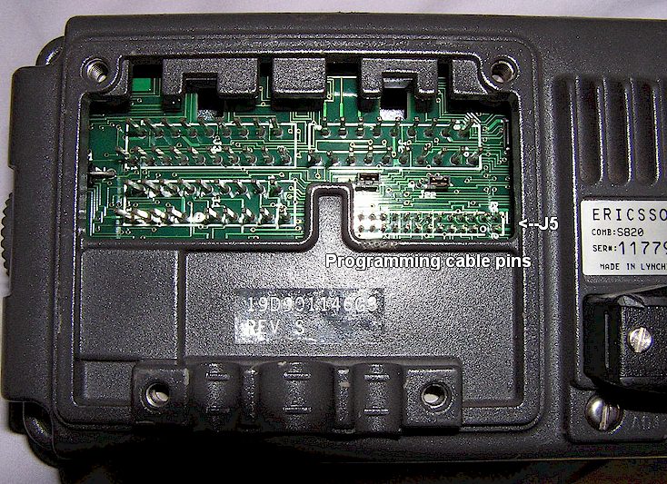
Where does the programming cable connect?
To the back of the control head at the siren-lights control connector, J5.
Where can I find Windows software instead of DOS?
You can't! These radios are over 30 years old, and they were manufactured in a DOS world. By the time Windows came into use, the RANGR was already obsolete and no longer in production. Nobody bothered to write Windows software for an obsolete radio. Maybe someday, someone will write a Windows based program for these, but at the moment, DOS or the suitcase programmer are your two choices!
I programmed an out-of band frequency 12 MHz out, using CONTROL-E, but it won't let me !
Control-E is a software over-ride which only works within a 10 MHz range outside the radio's design frequency range you entered when you built the radio personality. In other words, let's say you have a 450-470 range radio. You can use Control-E to enter 440 MHz ham frequencies (along with resetting the VCO coil) but it won't let you enter a 439 MHz ham channel. You have to modify the radio to become the different range model, and build the personality for that, if you want to go farther than 10 MHz above or below the design range of the model you select when you build the personality.
I get "Dwnld Error" even though the jumpers and cable are right!
Make sure you only programmed 16 channels per group if you have only one X2212 EEPROM in the radio. The maximum number of channels a radio drawer with a single EEPROM will hold is 16. If you have a radio with two of them, you can load up to 32. Exceeding the maximum number will give a download error message.
CAN YOU HELP?
"Flash" software: I need information on the "Flash" programming software for the regular (not CHP) S-820 and S-825, in other words, a list of what versions were offered and what the differences were. I also need a list of what the error codes on the CHP version heads translate to, for an upcoming web page on those.
REFERENCE SECTION
Downloading jumpers:
Before the S800 series heads will work with the radio involved, it will be necessary to make sure that the "downloading enable" jumper in the radio is set correctly. This is mainly important if you are using such a control head with an unrelated radio drawer where it is not known what kind of head was used with that drawer. Shown below are the jumper locations for the low band RANGR radios. In addition to the jumper being set correctly, the radio cable must be a downloading type. See information on that elsewhere on this page.
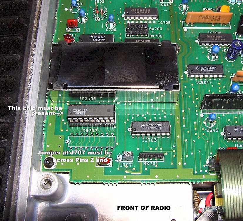
This is the location of the downloading jumper on a typical low band "051" suffix "RANGR 89" mobile radio, AXA9HHTR-163B series. To use with a downloading head, the jumper must be on the center and right pins, i.e. Pins 2 and 3. Note that the jumper is located elsewhere on the earlier RANGR "050" radios, see below.
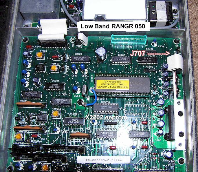
Below is the downloading jumper location on the first generation RANGR low band drawer, the "050" series with an FCC ID of AXA9HHTR-139B. To use the S800 series or S900 heads, the jumper at J707 must be across pins 2 and 3.
Where to connect programming cable:
Below is the rear area with the cover removed. The programming pins referred to as J5 are on the lower right.
TECHNICAL NOTES
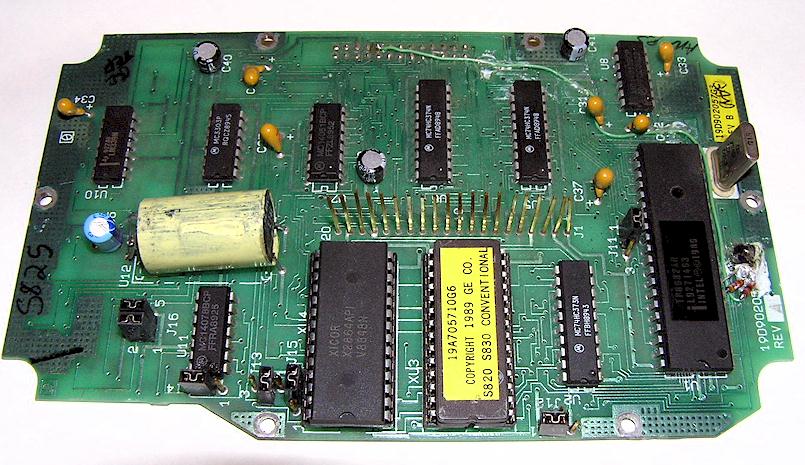
When you take the head apart, you will find it consists of three boards. The rear most board with the connector pins, the middle board with the CPU and ROM chips, and the front most board with the display and keypad. It helps to have several control heads in junk condition for parts, and in order to substitute boards to quickly find which one (ones!) are bad.
These heads are getting old. With that comes the failure of assorted tantalum chip capacitors, those tan colored plastic blocks found on the boards in these units. I recently had a couple of these fail on the CPU (middle) boards. You can usually tell this has happened by the smell of burnt electronics emanating from the head when you take the cable cover off the back, although usually there will be no obvious signs of overheating or damage. I use a Huntron Tracker 1000 to quickly analyze component signature traces in-circuit, but you can also just measure these with a multimeter and look for any shorted ones. Be sure to reverse the meter leads on any suspects to make sure you are not just reading a semiconductor junction downstream. A shorted one will read practically zero ohms in either polarity of the test leads. Unfortunately shorted tantalums on the CPU board seem to also take out the rear most (I/O) board, and I haven't found the fix for that yet.
The back-light inverter is that yellow cylinder on the middle board (see photos below.) Pretty simple, it's DC in and high frequency AC out to the back-light EL panel. A dark back-light can be a defective inverter module, although I have also found the modules to be perfectly good in heads with dead back-lights, because of a short on the back-light feed within the front-most board.
Note the photo below. This board is the older non-"flashable" CPU board.
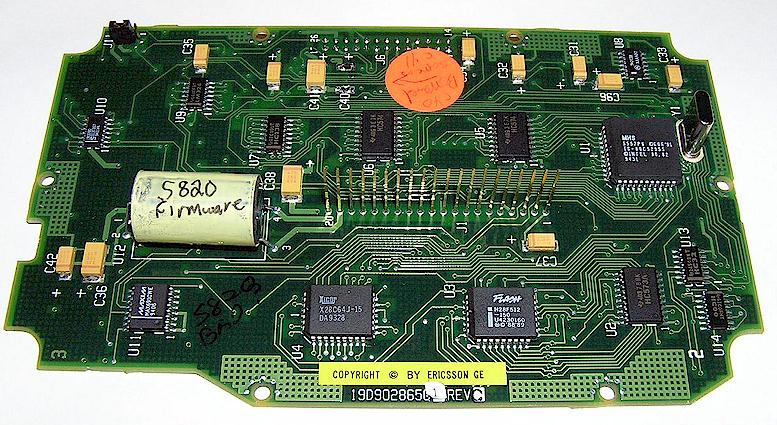
The board below is the newer "flashable" version. Note the smaller surface mount chips and the "Flash" logo on the ROM chip on the lower right.
References: S-825 Control Unit Manual, LBI-38244G
This page created by Geoff Fors, WB6NVH, Monterey California USA geoff @wb6nvh.com
Ver. 09/08/2024 © 2007 All Rights Reserved