HUMBLE MFG. CO.
Canadian Forestry Radios
There was nothing on the web about these interesting radios so I have put a page up about them and the company.
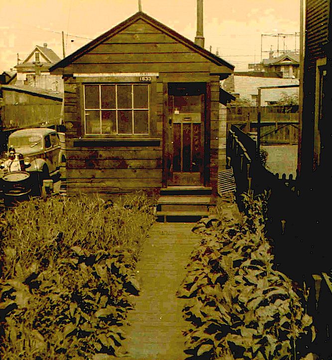
Humble Manufacturing began in a small building in the False Creek, B.C. area in the late 1940's and was founded by a WWII veteran who had been working for BC Telephone, the local telephone company. Humble made a variety of portable and mobile high frequency AM two-way radios, in wooden cases with wooden or metal covers. Humble is still in business, but left the radio manufacturing effort in the early 1970's to produce custom metal parts, which it still does today. The current Humble website is here:
Humble's first building:
Thanks to Ron Walsh of Humble for
the photo below
Shown below are the two radios I know about. If you have photos of others, please share them!
Type P-12 Models B through F
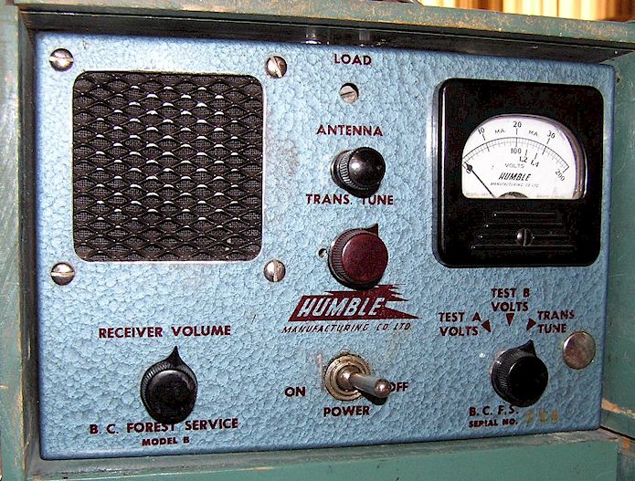
BC Forest Service
The one was obtained in September, 2010 through the kindness of fellow enthusiast and forestry radio historian Rick Ferranti, W6NIR.
These radios were used by the forest service in Canada as a 1950's version of the U.S. Forest Service Type SPF portable "smoke jumper" radio of the late 1930's. Humble advertised the sets as being useful for "field and exploration parties, lumber and pulpwood companies, timber cruisers on log drives, communication between barge and towboat, railway gangs, tractor trains and civil defense. This one is marked "BC Forest Service" on the front panel (British Columbia.)
Unlike the older Type SPF, the Humble set uses all miniature tubes. Five tubes are used in the transmitter and five in the receiver, as well as a pair of 1N34 diodes (presumably detector and noise limiter.) The transmitter puts out about 2 Watts on any frequency between 2-6 MHz. The receiver and transmitter are both crystal control.
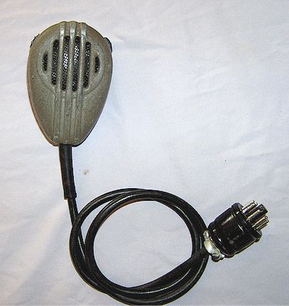
These seem be all the P-12 and I have seen Models B and F. Presumably there are others. The differences between B and F seem quite minor, such as that my B has a metal microphone while the F is plastic, and the method of attaching the PA tank coil differs between the two models. The Model B that I have says "BC Forest Service" on it while the F does not, and appears to have been used by a construction firm.
The case is thin plywood as with the SPF. Unlike the SPF, the batteries are contained in the bottom half of the cabinet. It is possible to carry everything needed within the cabinet of the Humble, unlike with the SPF, where a separate battery box and accessory kit were needed.
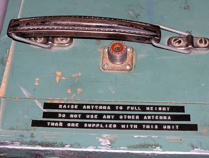
This example has a UHF connector added on the top panel of the cabinet, rather odd since the standard antenna is a Windom single-wire feed type (off-center fed) which does not use coaxial cable nor does it lend itself to this style of connector. There is a Dymo® label maker sticker set saying to use only the antenna supplied with the set and extended to its full height, leading me to guess that somewhere in its life a tall telescopic antenna was created for use instead of the Windom. Probably the WWII military surplus AN-75 (?) type used on the BC-659 infantry radio of WWII attached to a PL-259 connector. At 4 MHz, I can only guess that the performance of such an antenna must have been quite poor. The UHF socket is marked "Amphenol Canada," so it would appear this was done by the original user.
Presumably there were Types A and C through E. The literature refers to these as the Model P-12 Radiotelephone, and doesn't mention the different "types."
It appears that all these sets were supplied and serviced by Prairie Agencies, in Winnipeg, Manitoba.
The batteries required were two # 6 dry cell 1.5 Volt batteries, and four 45 Volt "B" batteries in series. Unlike the older Type SPF, there is no provision for CW and the microphone has a push-to-talk feature rather than the large transmit-receive lever switch of the SPF.
Prairie Agencies' literature makes a point of how much more advanced the Type B is than the old SPF, but in fairness, it's almost twenty years' newer, which also represents significant advances in technology and available parts, such as miniature tubes.
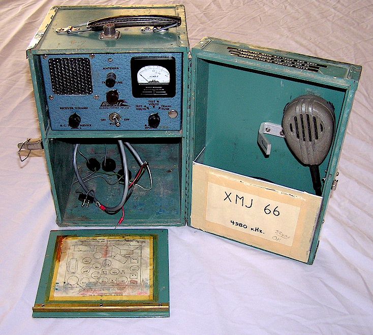
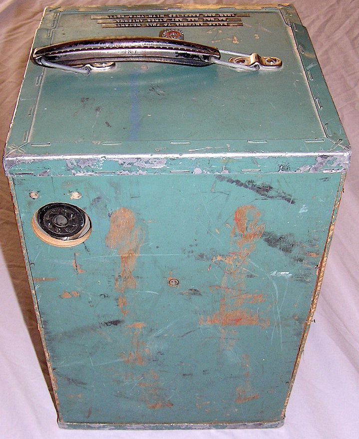
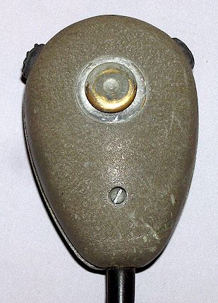
Note that the strange microphone has two push to talk buttons. I haven't figured out why yet. It terminates in an octal plug and connects at the rear of the cabinet. This is a later modification, originally the microphone was hard-wired and the cable came out of the area now filled with a nickel-plated "goof plug" on the front panel. Why this was done, escapes me.
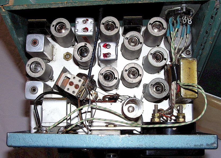
Rear view:
CORRESPONDENCE
In 2011 I received a note from Andy Woodsworth, from Victoria BC, about his experiences with this Humble radio in the BC Forest Service back in the era when these were originally used, and I pas sit on here:
I spent our summers with the BCFS in the mid-1960's in northern British Columbia. We used these radios on so-called "fly camps" - we would [travel] from our base camp to smaller camps, mostly by helicopter (Bell 47) but sometimes by river boat. The camps were usually a week long. The radio was our only contact with the outside world and was primarily for emergency purposes, but we would check in with the base every evening. The antenna was just a long wire that we strung between trees. The key thing we had to remember was to take it down again before the helicopter arrived to pick us up. Even on the Model B we could hear other stations from all over northern British Columbia on a good evening, including fire lookouts.
BCFS at that time operated a province-wide radio network, and our base camp had - as I recall - a 1 KW transmitter that could easily talk to Victoria from where we were, near the present day town of McKenzie. The antenna for this was a big wire strung between tall poles. They used a Radiogram form for passing messages.
In my last summer in the bush, they installed a VHF repeater on a mountaintop and started phasing in hand-held VHF radios instead, but it was iffy (you had to be in a position that could "see" the repeater .) The current radio network is much more sophisticated
http://www.for.gov.bc.ca/his/radio/Overview/overview.htm
Thanks for putting up the photos; they really took me back to the 60's!
Andy
RESTORATION PROGRESS:
So far I have found that all the paper capacitors broke down at 100 Volts, and they have been replaced. The resistors measure within tolerance, which was a surprise, and all the tubes tested as very good. Interestingly, the B+ is applied to the transmitter and receiver at all times. The PTT switch in the microphone switches the filament voltage from the receiver circuitry to the transmitter and activates the antenna relay.
One surprise was finding that the meter was open circuit. In removing the meter, it was obvious that it had been out before, by the missing nut and lock washer on the hardest-to-reach stud. Removing the meter from its case showed that a connecting wire to the front spring pivot assembly had been improperly replaced on the outside of the magnet assembly instead of behind it, and the case assembly had cut through it on reassembly. After replacing and properly routing the wire, the meter then functioned fine. Unfortunately, someone had managed to break the plastic tip off the inside end of the mechanical zero-adjust screw, so I had to manually adjust the zero with the case off and leave it at that.
Powering up the filaments was the next step, but the meter still read zero! It was then realized that the meter only comes into the circuit when the set is in the transmit mode. Keying the mike then showed filament voltage, but at an unacceptable voltage drop. The filament power travels through the microphone cord. The non-stock connector for the mike at the rear apron was found to be contributing to this. The plan is to return the mike connection to the stock configuration, and then measure the DC right at the tube sockets to check meter calibration.
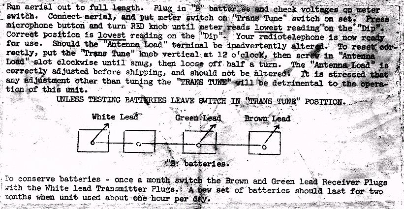
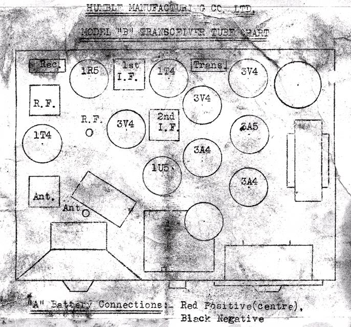
Here are scans of some rather deteriorated tags found inside. They are also provided as Adobe® PDF documents so you can print them. I cleaned up and redid the instruction sheet, the component layout page will take a bit more time to clean up.
CLICK HERE FOR A PDF OF THE ABOVE LAYOUT
CLICK HERE FOR A CLEANED-UP PDF OF THE INSTRUCTIONS
Humble Base Station
Model Unknown
This is a larger Humble unit apparently intended as a fixed station to communicate with the Humble set shown above. Unlike the portables, it has multiple channels. Based on the battery test function, this too was probably intended for field use, but probably in a fire lookout tower or something similar.
Photo courtesy Ron Walsh of
Humble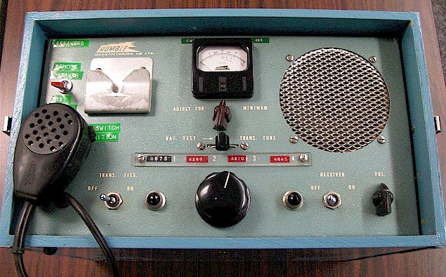
When time permits I will add copies of what documentation I have on this set to this page. If you have a schematic or a manual on this radio, please contact me so that we can share this information! I can be contacted at Geoff@ wb6nvh.com.
Ver. 10/27/2025 © 2010 Geoffrey C. Fors All rights reserved