
Russian
Lavina M Radio Transceiver
Geoff Fors, WB6NVH
The Russian Lavina (Lawina) M transceiver is a 160 and 80 Meter CW transceiver, made for novice level amateur radio field use in the former Soviet Union in 1989 and later. Its primary purpose was in the training of DOSAAF members ( a paramilitary kind of scout organization.)
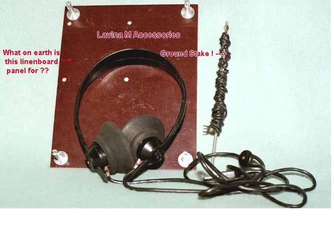
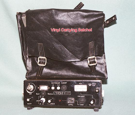
The frequency coverage is 1800-1935 KHz and 3500-3625 KHz. As originally supplied, the radio came with a leatherette carrying satchel, a key, headphones, an AC line cord, a DC patch cord, a grounding stake, an antenna consisting of a number of aluminum rods, and a rather strange thick phenolic plate which is intended as an operating desk, and contains a slide-in bracket into which a key could be affixed as well as a set of four twist-lock pointed rods which act as legs.. There is also a protective front cover, which affixes to two knob-like clips on either side, but my example did not come with one, nor did it include the antenna sections or the key. Presumably, some sort of instruction manual was also furnished.
My radio was obtained from a Lithuanian ham via eBay. He had three or four of these, and the others are also now in the USA.
The power output is a nominal 70 mw. The receiver sensitivity is better than 1 uv. Construction quality is good, but below the level expected from Russian military equipment of the same era. The Lavina is fully solid state, using one IC and a number of bipolar transistors and several FET's. The outer case is a thick yellowish plastic of unknown composition, possibly butyrate, and the front panel is a milled and engraved aluminum plate. The set is nominally weatherproof, with rubber boots over the pushbutton and toggle switches and rubber 0-rings on the adjustment hole threaded caps.
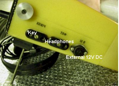
Power is supplied by 20 internal AA nicad cells, arranged in two banks of 10 in parallel with each other via diode isolation to supply a nominal 12 volts. It is also possible to operate the set via an external 12 Volt DC source, using the "12B" jack on the right side of the case. That jack is a standard 2-pin European DIN connector, the opposite of good engineering standards in that the exposed male pins of the external power source will be hot with DC power prior to insertion into the Lavina. A typical source for a matching connector is European car stereo wiring harnesses. Dealers of Becker and Blaupunkt German auto radios may stock these connectors, and they are also found in the accessories supplied for old Grundig and Telefunken home stereos and tape equipment. The headphone and key jacks are standard old-style European AC line cord 2 pin plugs.
The Lavina M operates in full break-in mode; the key plugs into the front most jack on the right side and simply shunts the high side of the jack to ground when depressed. The antenna appears to have consisted of eight rods approximately 11 inches in length, which lock into each other, making an approximately 8 foot long whip. The antenna threads into the swivel stud on the radio antenna insulator assembly and consists of aluminum tubing sections topped by a star-shaped capacity hat.
There is a provision to charge the internal batteries from an AC source, via a front panel 220V AC socket located just to the left of the on/off switch. A red LED then indicates AC power and that charging is taking place. Power to the charging system is continuous and independent of the on/off switch, despite the confusing labeling on the front panel. A 100 KHz crystal calibrator is fitted, and there are two "correction" variable trimmers accessible via the front panel, behind screw-cap seals, for adjusting the dial calibration. It was found that the dial calibration nonetheless does not hold from one end of the tuning scale to another, being off some KHz at the opposite end from where calibration takes place. The user is left with the choice of making dial calibration accurate at one or the other end of the dial, or perhaps making his favorite band segment accurate. A better and simpler design would have been a movable dial cursor, as on equipment of the 1950's.
The color schemes vary somewhat. Other examples have blue cases and/or white knobs.
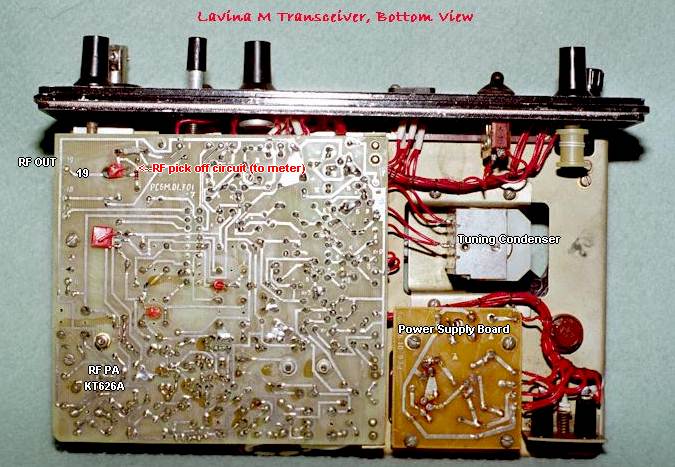
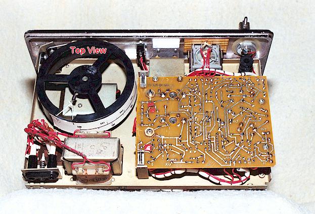
Internal construction consists of two circuit boards which face each other, on a sheet steel chassis. There is a small third circuit board which contains the AC power supply filter and regulator components. A vexing discovery was that the wiring harness uses wire of all the same color ! This makes troubleshooting difficult. There is a great deal of room between components, however for some reason the traces on the printed circuit boards were drawn very close together, in some cases almost shorting . The circuit board was created by hand drawing rather than a CAD program, and the board material appears to be G10 or equivalent epoxy. The transistors and FET's are all Russian types which in most cases cross to Japanese equivalent numbers. At the time this was written, a schematic (such as it is) can be found on the web at:
http://www.cqham.ru/sch_eng.html
and a cross reference to most Russian transistors can be found by searching with Google. Also, an interesting photo gallery of Russian military and civilian radios can be found at
http://hamradio.online.ru/trx/
On the air:
Initially, one would pound the silly ground stake into the earth and assemble the antenna rods. Then, using the Lavina consisted of simply picking the frequency, keying the transmitter, and adjusting the antenna tuning for maximum RF output into the antenna as viewed on the meter. The antenna tuning control moves a slug in and out of the series inductor in the RF output line, but seems to have no effect on the receiver. The antenna circuit is designed to load the 8 foot whip to at least a 3/4 scale reading on the "Antenna Voltage" meter. It will not (in its native form) successfully transfer power to anything else. I first tried attaching a 60 foot random wire to the antenna stud, but could not get any reading on the "Antenna Voltage" meter. The original antenna is so short both electrically and physically that little energy gets radiated, spoiling the range and potential of the transmitter. On the other hand, had the transmitter been designed for 50 Ohm operation, some sort of lossy tuner would have been needed as an accessory in order to feed the short whip antenna. I found that it was possible to load a random wire antenna by inserting a series ceramic or mica capacitor of 50 pf or less in series with the antenna lead. Exactly how much capacity depends upon the length of the random wire.
The receiver has high gain and seems happy with the short whip antenna, but is not "upset" when fed with a long random wire.
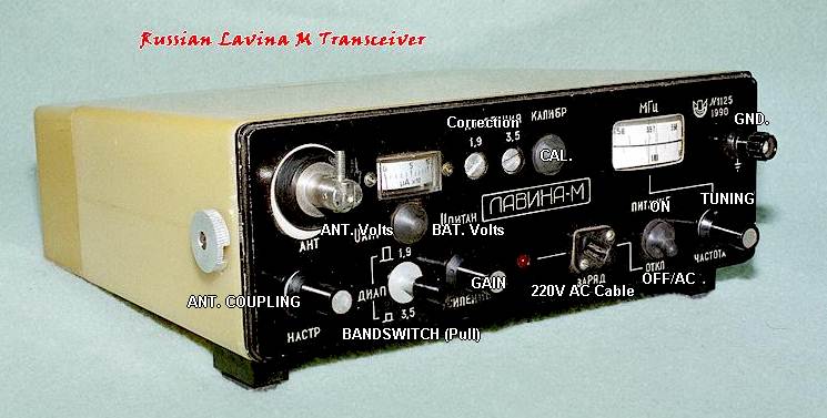
Using the calibrator consists of depressing the "KALIBR" knob (closest cross to the Cyrillic writing, see below) and tuning in the 100 KHz interval signal. The dial lamps should also illuminate at that time. There are lamps on the meter and the tuning dial. If the displayed frequency is in error, one removes the protective screw over the trimmer for the appropriate band, found next to the calibrate button, and adjusts that trimmer for zero beat.
An external RF amplifier would seem necessary if serious attempts at making contacts are considered. Perhaps something that would raise the power output to approximately 5W, which could be built into an accessory case along with a speaker/amplifier and a large 12V gel-cell battery with charger?
The power supply, as mentioned, requires 20 AA size nicads. The original Russian cells were only 450 Mah and it is easy to find much higher capacity cells on the surplus market. Some cells found today, such as cell phone surplus NiMh cells, are slightly shorter than the standard AA yet provide 1800 Mah capacity. However, most "unused" or "overstocked" NiMh cells being sold by mail order and web surplus vendors come assembled in cell phone battery packs, made in China. It has been my experience that most, if not all of these cells are bad right out of the package and it's fairly difficult to expect a refund if you've smashed the pack housing to extricate the cells. I suggest only buying cells that come with a warranty, and avoiding anything made in China. It also helps to buy cells with solder tabs on them, as they are much easier to work with.
The accessory headphones terminate in a standard European AC power plug (two round prongs.) They are primarily plastic but well made and reasonably sturdy. The sponge rubber oversized ear cushions are reminiscent of US military WWII headphones and comfortable.
Shown below is a translated layout of the front panel and a drawing of the case to transceiver power connections.
This page created by Geoff Fors, WB6NVH, Monterey California. If you would like to contact me, you can do so by e-mail to geoff@ wb6nvh.com. If you have any other information on these radios, an antenna, or any other accessories, I would love to hear from you!
Ver. 2/14/2009