REGENCY SCANNER MODIFICATION INSTRUCTIONS
Band Expansion for Models M-100 and M-400
Geoff Fors, WB6NVH
The Regency M100 scanner was purchased in large quantities by a number of state highway patrols and municipal agencies in the early 1980's, and later surplused. Today they are frequently found at flea markets and on eBay at bargain prices. As supplied from the factory, the Regency M100 and M400 scanner firmware will not allow input of frequencies below 30 MHz or above 50 MHz, nor will they allow input of government frequencies below either 144 MHz or 440 MHz. This most vexing situation is easily corrected. The conversion consists of first installing the "limit test" jumper, and then adjusting the VCO coils as necessary to insure that the VCO locks at both extremes of a given frequency range. No other test equipment is necessary.
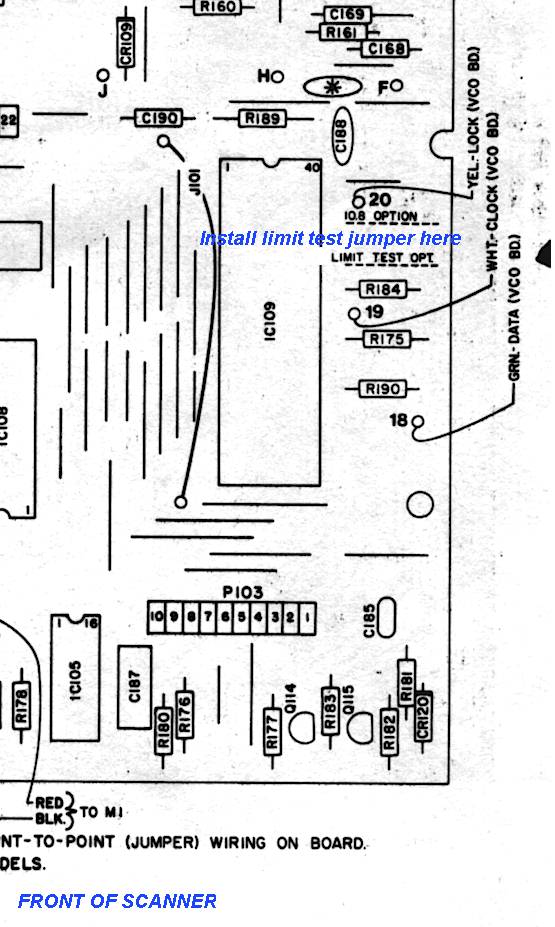
Step One: First, remove the covers and locate the limit test jumper location on the main pc board of the scanner. This is located near the large socketed CPU IC, as shown in the drawing below, and is called "Limit Test Opt." . Install a jumper. To do this properly, you'll have to remove the bottom plate.
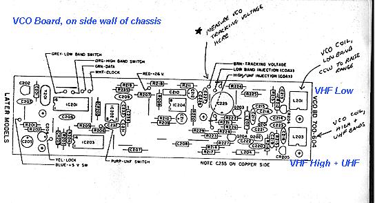
Step Two: Locate the test point on the VCO board as shown on the drawing below, which is where the brown wire connects. There are two VCO coils; one exclusively for the Low Band and the other for both the High VHF and UHF bands. The upper VCO coil handles only the low band (30-50 MHz), while the other one handles the VHF High (130-174 MHz) and UHF (400-512 MHZ) frequency bands. Measure the voltage at the brown wire test point, and make sure that the VCO voltage is within range when entering frequencies at the lowest and highest extremes of the range you want to cover. The VCO voltage will change from approximately 14 volts DC at the upper extreme to 1.3 volts DC at the lower extreme for the VHF high and UHF range (all the same VCO tracking rage), and 1.8 and 17 Volts for the VHF low band range.
The procedure is as follows: Enter the highest UHF channel desired, then check the VCO voltage. Enter the lowest VHF high band channel desired, then check VCO voltage. The extremes should not exceed 1.3 Volts at one end and 14 at the other. Then enter the highest VHF low band channel desired, and measure the VCO voltage. Then enter 29.4 MHz and measure the VCO voltage. The high and low extremes of the VHF Low Band VCO must be within the range of 17 and 1.8 Volts DC, respectively, or at least such that the VCO locks reliably (especially during scanning). Unstable scanning speed is a sign that the VCO is not reliably locking and that the tracking range needs adjustment.
Please note that there is some compromise involved on the VHF high and UHF frequencies, i.e. you usually cannot get the VCO to lock reliably at one extreme or the other if you choose too large a frequency spread. For example, you will not be able to program frequencies in the 406 MHz range and be able to do so on the 510 MHz range as well. However, it is possible to expand the low band range to 29-54 MHz without any unlocking problems, and to cover the 140-170 MHz range successfully.
It should not be necessary to realign any of the front end coils after this modification. They are sufficiently broad-banded. The only test equipment necessary to make this modification is a good DC voltmeter.