
MOTOROLA
FM
POLICE RADIO EQUIPMENT
Part One, 1941-1957
Introduction
The Galvin Corporation created what they argued was the first production AM broadcast car radio, in the early 1930's. Up through the mid-1930's, they also made specially modified car radios to receive police broadcasts, on a "to order" basis fro nearby police departments. These were the days when the company was small enough that one could walk in off the street and have a special modification of a radio done almost "while you wait." Galvin began producing "Motorola" brand mobile AM police one-way radio equipment in 1937, with a modified broadcast automobile radio first called the "Police" and later dubbed the "Police Cruiser." In approximately 1939, Galvin introduced two-way operation with the T-69-20A mobile police transmitter, a VHF AM two-piece unit which operated in the 30-40 Megacycle range. Base station transmitters and receivers were also produced to communicate with this mobile equipment. The pre-war Galvin AM equipment is detailed on its own separate page, PREWAR MOTOROLA POLICE RADIO.
Deluxe Line (1940-1950)
In 1940, the Connecticut State Police adopted a VHF FM two way system in the 39 MHz band, manufactured by Fred M. Link's Link Radio Corporation. The Link contract was the first large scale two way FM VHF system in the country and was so successful that it was held out as a model for other departments to emulate. It should be noted that many articles, and Link's own advertising at the time, give the impression that Link was first with an FM VHF two way radio, but this is not actually the case. GE had purchased a license to pursue FM development from Major Armstrong, inventor of FM, and had produced working VHF FM equipment since approximately 1938, although it was essentially experimental without meaningful sales. This equipment had been examined by Professor Daniel Noble, consultant to the state police, however he found it "unsatisfactory" for reasons not fully disclosed. The Fred Link system was built to Noble's specifications, by modifying existing VHF AM equipment (the 8-UA receiver and 15-UBX transmitter.). Noble would shortly thereafter join Galvin Corporation and supervise the production of Galvin's own line of two way FM radios, which not coincidentally looked very much like original Link equipment, and was in direct competition with it. This first line of Galvin FM equipment was dubbed the Motorola "Deluxe" line, and Galvin at that time ceased design of any new "Police Cruiser" receivers or T-69 series AM transmitting equipment (although production of both continued throughout the remainder of the 1940's.) Fred Link encountered financial difficulties and sold Link Radio in 1950, undoubtedly due to the competitive pressure from much better funded Motorola.
The Deluxe line consists of a two piece radio set, mounted in the trunk of the vehicle. Unlike the Link FM equipment, the Motorola equipment placed the vibrator power supply for the receiver inside the receiver cabinet, rather than in a separate external case. Perhaps by virtue of being approximately a year newer than the Link equipment, the Motorola was more advanced in design (as well as being more complicated.) The Deluxe line was produced from approximately 1941-1950, at which time it was replaced by the "Research" line, Motorola's new flagship two-way radio product.
During its production run, the Deluxe line was produced in many configurations and models, for both low band (40 MHz), mid-band (75 MHz) and (later) high band (150 MHz) systems, and was sold throughout the world. The equipment would later be referred to colloquially as "Coffin Units" or "Doghouse Radios" by the two-way radio trade.
The transmitters and receivers were labeled individually with model numbers, FMR- for the receivers and FMT- for the transmitters. After the end of the war, a "U" was added denoting high band VHF, for example FMTU-30D. There were various model numbers within this scheme; the FMAR-13V receivers, for example, were low band sets of a newer design than the original 1941 sets, used Loktal tubes and were called the "Precision Selectivity" receivers. The original low band receiver was the FMR-13V. The transmitters were available in various power levels and power supply types, and included such numbers as FMT-16V for a 20 Watt vibrator powered low band transmitter, to the more common FMT-30D dynamotor powered 30 Watt transmitter. All of the Deluxe Line began as 6 Volt DC powered equipment, although some military applications were supplied with 12 Volt and 24 Volt power supplies. Eventually some of the equipment was converted to 12 Volts in the field when American automobiles changed to 12 Volt batteries, although the majority were taken out of service and scrapped at that time.
A complete model would be numbered something like "FMTR-30D" or "FMTRU-30D," the complete model number apparently taking the transmitter numeric model number rather than that of the receiver. The complete model number only appeared in the manuals and not stamped on the equipment itself.
Shown below is the earliest Deluxe line design. Later versions had a pull-handle cover latch instead of the top mounted twist handles. Note that there are a couple of ways to tell a high band from a low band Deluxe set in old photos. The low band sets use prewar "Bendix" style antenna connectors which have a smaller tightening ring and are generally smaller in appearance than the more modern "UHF" Amphenol connectors, which were used on the high band sets. Also, on the high band transmitters, there is a small "coupling" screw adjustment hole located on the panel on the left end just above the antenna connector. The antenna connectors in the photo below with the legend "Mobile Transmitter and Receiver" can be seen to be UHF style, therefore those sets can be identified as VHF high band.


Dispatcher (1947-1952)
The Dispatcher was an "economy" series of two way one-piece radios created in approximately 1947, probably as a response to the FCC's opening the VHF "high band" 150 MHz channels in 1946, requiring that new police licenses be on that band absent a showing of need to still use low band. The Dispatcher was the forerunner of the Research Line, which would eventually replace the Deluxe series in the early 1950's. Unlike the Deluxe equipment, the Dispatchers were built using miniature tubes on two small channel-shaped chassis (called "strips" in the industry) and unitized into a single slide-in cabinet with an optional key-lock (called the "drawer" in the industry.) Dispatchers offered only a low power transmitter, in the 10 Watt range, and were available in either low or high band VHF. The Dispatchers were typically numbered FMTR-5(V) (low band) or FMTRU-5(V) (high band), and were known as the "5V" in the industry. Because of the small size of the strips in the Dispatchers, they were also mounted in black steel Harley Davidson "tubs" and placed in the saddlebag area of police motorcycles. The cables and control head for the Dispatchers do not interchange with the Deluxe line. The Dispatcher used a circular connector of the Cannon AN- series (later re-designated MS-) and the new Amphenol "UHF" connector for the antenna socket. Unlike the Deluxe Line, the Dispatcher control head could offer a microswitch under the microphone hang-up clip which would shut off the transmitter tube filaments when the microphone was hung up after use. The microphone hangs on the front of the control head itself in Dispatcher installations.
The Dispatcher "drawer" consists of only two chassis; the receiver chassis and the combined 10 Watt transmitter/power supply chassis which used 2E26 tubes in the transmitter power amplifier. The receiver used all miniature tubes and offered somewhat less sensitivity than the Deluxe line, and used a "derived" IF section which was not crystal controlled. The receiver had rather poor selectivity. The Dispatcher transmitter used a 2E26 output tube and the power supply consisted of a synchronous vibrator for the receiver and a non-synchronous vibrator for the transmitter, rectified by a 6X5 octal based rectifier. The Dispatcher transmitter was of course wideband FM, and like the Deluxe line, there was no deviation control offered.
It appears that there was no specific speaker supplied with the Dispatcher series; initial models seemed to have been supplied with the square louvered speakers later used on the Research Line radios of the 1950's. Some sets were ordered without speakers, as it was popular at the time to make use of a broadcast radio speaker mounted behind the grille of the car's dashboard at its intended place. Few fleet automobiles were purchased with radios (or even heaters!) so the space was available and represented a cheaper and better alternative to the purchase of a stock Motorola speaker.
The Dispatcher was widely used in taxi fleets and small police departments, but was produced only for a few years, approximately 1947-52. The low transmitter power and rather dismal receiver sensitivity on VHF high band limited the Dispatcher to small geographical areas. Most Dispatchers seem to have been made for the VHF high band range. Additionally, new FCC restrictions on stability and narrower channel spacing were on the horizon, and Motorola chose to discontinue the Dispatcher and bring out a totally new model rather than attempt to upgrade the original design.
The model name "Dispatcher" would continue to be used over and over again in succeeding years, with newer models, for example the "Transistorized Dispatcher," the "Industrial Dispatcher," the "Airport Terminal Dispatcher" and the "Solid State Dispatcher."


The 1948 photo below shows an FMTRU-5V mobile leased to a police department
by the Bell System. In the northeastern states, the Bell System was
heavily involved in leasing two way radios and mobile telephones to police and
fire departments. Apparently the Bell System felt that handsets were
better than microphones, and the majority of installations featured a handset,
such as in the photo below. This made for somewhat of an odd appearance,
since the 5V head is unique in having a microphone hanger on the front panel.

Research Line (1949-1952)
The Research Line was introduced in 1949 to replace the aging Deluxe equipment and was the basis for one of the most successful and reliable two way radios of the decade. The Research Line was an extension of the concepts introduced with the Dispatcher sets, namely one-piece radio drawers using replaceable strip-chassis, with miniature tubes in the receivers. Unlike the "5V" Dispatchers, the Research Line was available in many different configurations and with many different receiver or transmitter chassis combinations. The receivers offered in the Research Line included "Unichannel" and "Sensicon" types. The Unichannel receiver was a narrower chassis version, less expensive, but with approximately the same performance specifications as the Sensicon. The Sensicon receiver was the most expensive version, and was on a wider chassis than the Unichannel. In the VHF high band version, the Sensicon receiver had tunable cavity "pipes" in the front end (Sensicon "A".). Both types of receivers featured Motorola's new "Permakay" IF filter, for "Precision Selectivity," although they could be ordered without it (few were.) The transmitters were available in power levels from 10 to 60 Watts, the higher powered transmitters having a wider chassis and using an 829B or two 2E26's as the final amplifier/s.
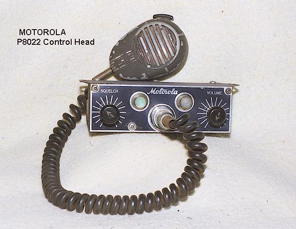
Depending upon the chassis selection, the Research Line sets could be purchased in a 10" wide cabinet or a 15" wide cabinet (or specially ordered in an even wider case !). All Research Line mobiles used the same control head, although that control head was available in many different configurations. The Research control heads are recognized by their white ribbed knobs with black pointers and the "squelch" and "volume" nameplates being riveted to the panel plate. Research was produced from approximately 1950-1955. Research also was the first series to offer a 450 MHz UHF radio, near the end of Research model production in approximately 1954.
Typical Models:
It is probably impossible to list all the model combinations which were possible in the Research Line. The most common ones were the "41V", the "80D", and the "140D" series.
41V: The FMTR-41(V) and the FMTRU-41(V) were the smallest and possibly the most popular sets of the Research Line. They were in a 10" wide case and featured the Unichannel receiver with a 10-15 Watt level transmitter, with a third chassis containing the separate power supply. The 41V used a vibrator power supply with a selenium rectifier, and was available in one or two channel models. Unlike its predecessors, the 41V has an adjustable deviation control on the transmitter. The 41V was available in either 6 or 12 volt versions, but not both in the same chassis. Unlike any other equipment either prior to it or contemporary with it, the 41V was available in either a dash mount or a trunk mount configuration, as well as a desktop base station.
40V: The FMTRU-40V is an interesting set which appears to have been made primarily for the VHF high band taxicab market and seems to have been intended as an improved version of the older Dispatcher "5V" series of equipment. It consisted of a wide chassis high band Sensicon "A" receiver, mated to a Dispatcher transmitter/power supply combination, in a 10" wide cabinet. This is unusual in that the Dispatcher equipment was already discontinued at the time the 40V was being sold. Evidently Motorola had a surplus of Dispatcher transmitter/power supply combinations left over. The choice of a Sensicon A receiver rather than a Unichannel receiver is also interesting; evidently the set was designed to be used in urban areas with a high concentration of interfering signals and intermodulation distortion, which only the Sensicon A receiver with its cavity-pipe front end could deal with. Otherwise, had a Unichannel receiver been used, the set could have been significantly narrower and compact. Most of the FMTRU-40V sets seem to have been sold in the San Francisco, California area to taxicab operators.
80D and 140D: These were the industry standards in the 1950's and made in the greatest quantity.. The FMTR- or FMTRU-80(D) and FMTR- or FMTRU-140D are 15" wide cased mobiles which usually used Sensicon receivers with high power transmitters. In some instances, a less expensive "Unichannel" receiver was used. The 80D used a pair of 2E26's while the 140D used a single 829B in the transmitter power amplifier. The 80D was nominally a 30 Watt transmitter while the 140D was nominally a 60 Watt transmitter. The power supply used a vibrator for the receiver and a dynamotor for the transmitter. The Research Line enjoyed widespread popularity and such a long service life that most of them were converted to 12 volts after the auto industry switched battery voltage standards in 1956, and many were also converted to comply with "narrow band" FM requirements mandated by the FCC in the early 1960's. In the mid-1960's, Motorola even offered a field modification kit which replaced the vibrator/dynamotor power supply in the 80 and 140 series with a 12 Volt transistorized power supply, which included a heat sink which bolted to the front panel and instructions to overstrike the model number on the ID plate to read FMTR-140(T) or FMTR-80(T) as appropriate. The chassis used in these mobiles were also used in all manner of upright cabinet base stations, desktop base stations, repeaters and so forth.
AC Utility: The AC utility was a desktop base station configuration made from an FMTR-41V series mobile configuration, using a built-in speaker and control panel along with an AC power supply in place of the mobile power supply. Full sized tabletop base stations were also marketed, unlike the Deluxe Line era when the mobile chassis were either used in their usual housings or mounted in six foot rack cabinets.
AM Options: Many large police departments still used medium frequency AM for their car to station frequency into the late 1950's (Los Angeles even into 1965!), but the old medium wave separate Police Cruiser receivers were no longer produced after 1950. To address this market, Motorola offered a medium frequency AM receiver strip which could be used inside a Research Line case instead of a Unichannel FM VHF receiver, either with a companion VHF FM transmitter or by itself as a one-way setup. That AM receiver was the P-9075, which was also available in a motorcycle version in a Harley Davidson steel saddlebag box.. A typical configuration might have been an FMTR-5(V) style motorcycle radio but with this AM receiver in it instead of the VHF FM receiver. The model numbers of such sets are not known to the author, but may have been something similar to "FMT(A)R-5(V) or "FMT(A)RU-40(V)SP-xxx." This receiver chassis was built at least through the end of 1955.
Research model numbering change: In approximately 1954, the model numbering scheme was changed from the FMTRU- type numbers to ones usually beginning in T43-1 or T51-1 type series, although the equipment otherwise appeared identical. At the time of this change, the T44-1 UHF mobile was introduced, which was in a 15 inch housing and continued with few changes into the new "Twin-V" series after 1956, other than being re-badged "Twin-V" with a model number change to "T44AAV."
Second Generation Research Line (1953-1955)
The Research Line rather quickly evolved from the initial offerings of the "80D" and "140D" sets to a wide variety of configurations in 1953, in addition, Motorola changed the model numbering scheme, abandoning the FMTR- style system to one of a series of numbers such as T51-1 or T43-1, being further expanded to such numbers as T51G-1. In 1954, a UHF radio, the T44A-6 was also developed. Differing series of chassis became available, now the "A" or "G" line series. The "A" series chassis were essentially the same as in the FMTRU-80D or -140D equipment, including the famous "Sensicon A" receiver. The "41V" series mobile chassis strips were discontiuned at this time and the "41V" was replaced by the T41G or T43G series radios, using the same housing but featuring the new "Unichannel" style "G" chassis for both transmitter and receiver. The wider cased higher power radios were also available with the "G" series "Unichannel" chassis inside, in which case blank metal filler chassis strips were added to fill the space in. The array of available configurations in the second generation "Research Line" was large. As mentioned, most of the Research Line mobiles were capable of either 6 or 12 Volt operation by the selection of appropriate cables and jumpers on the chassis, but apparently for marketing reasons, Motorola chose to rename the standard mobile radio line the "Twin-V" in approximately late 1955, even though it was largely unchanged from the second generation Research equipment.
Portable Sets:
Motorola's portable sets were offered in two models, starting in 1947. The portables are probably most appropriately called Research Line portables rather than Dispatcher or Deluxe portables, although they actually have nothing in common with either equipment series.
FHTR Series: The lower powered portables were the FHTR- series (FHTRU- for high band). They make use of subminiature wire-lead tubes in individual modules, and were powered either by a pair of 2 volt wet cell batteries with a vibrator power supply in a large battery box, or several 67.5 volt "B" batteries and a string of "D" flashlight cells in a smaller "dry battery" box. The FHTR series was available in one or two channel models, and could be ordered with extra transmitters or receivers inside for broad band operation. There was no speaker, only a handset which hung on a cradle across the top. Most handsets appear to have been supplied by Roanwell. There was no squelch in the receiver on most models, although it was an option, with the squelch control a screwdriver adjust potentiometer located inside the power supply.. Evidently the additional battery drain of the constant noise in the earpiece during no-signal conditions was offset by the savings in not using an additional tube and module for the squelch function. The FHTR- modules and basic design were incorporated into a custom made forest service semi-portable repeater station called a "lookout radio," which as the name implies, was used in forest service lookout towers throughout the country. This series appears to have been discontinued by 1954.

FPTR Series: The higher powered portables were the FPTR-series, and came in a much larger and different case than the FHTR- sets. The FPTR units had a large chrome handle across the top and offered a speaker/microphone combination rather than a handset. They also offered squelch in the receiver, although that squelch was a relay-operated type rather than an electronic design. Like the FHTR units, there was a battery box across the bottom where large B batteries resided. The FPTR units use most of the same modules as the FHTR- sets. The FHTR equipment seems to have been discontinued at the introduction of the Research Line, but interestingly, the FPTR- equipment continued to be sold at least through 1957 after being re-numbered as the P11-1 (low band) or P13-1 (high band). Some are painted with gray wrinkle paint, while others are a silver-gray hammertone finish. I am not sure which is newer. An accessory AC-DC power supply was offered, which connects to the external power connector on the top panel of the equipment. Note that the microphone in the example below is a slightly later model; the one used with this model is a longer round style made by Shure, rather than the Turner manufactured item shown here.

MOTOROLA MODEL NUMBERING SYSTEM, 1942-54
(Deluxe, Handie Talkie, Dispatcher and Research)
Typical model numbers broken down, for complete sets:
"FMTRU- 30(D) " would be the model number of a complete set, as follows: FM= FM equipment, TR = transmitter and receiver, U = "UHF" (150-174 MHz), 30 = model series, D = dynamotor. The FMTRU-30D would usually consist of the FMRU-16V receiver and the FMTU-30D transmitter.
"FPTR-1" would be the model number of a "high power" speaker type pack set, low band, as shown above. The "H" as in FHTR-1 would refer to a low power handset model, as shown above.
Individual unit model numbers would be as follows:
FMR-13V would be a low band FM receiver only, vibrator powered, 13 series, low band (no "U.")
FMT-30D would be a low band FM transmitter only, dynamotor powered, 30 watts
THE TWIN-V AND REPLACEMENTS FOR THE RESEARCH LINE:
By late 1955, Motorola had begun production of a replacement for the Research Line, called the Twin-V series, named so because of their ability to work in either 6 or 12 volt vehicles depending upon the selection of power and control cabling. The American auto industry had begun the switch to 12 volt batteries in 1956, and by that time practically all Motorola Research mobiles were 6 or 12 volt compatible. This was accomplished by split transformer primaries and dynamotors with dual windings.
The Twin-V series differs little from the original Research Line, except for an expanded choice of optional receivers and transmitter power levels, and all mobile models being configurable for either 6 or 12 volt input. The transmitter and receiver strips from the Research Line were upgraded to feature more modern tube types but were otherwise variations of the same theme. The original Research Line mobiles, in the second generation type numbering scheme, continued to be made for a few years into the Twin-V era.
My plan is to create a separate history page for the Twin-V and successive radios, e.g. from 1957-1970, hence this history page stops at 1957, the year the Research Line was phased out.
This page created by Geoff Fors, Monterey California. Copyright 2000, all rights reserved.