MOTOROLA
FM
MOBILE 2-WAY RADIO EQUIPMENT
PAGE TWO
Portable Sets to 1957:
Motorola's portable sets were offered in two models, starting in 1947. The portables are probably most appropriately called Research Line portables rather than Dispatcher or Deluxe portables, although they actually have nothing in common with either equipment series.
Please note that the portables described below are all VHF FM types. Motorola did manufacture high frequency AM versions of these specially for the U.S. Forest Service. I have no photos or documentation of such models, so any help is solicited!
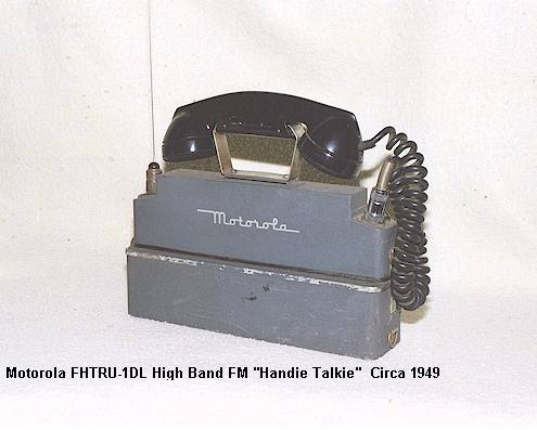
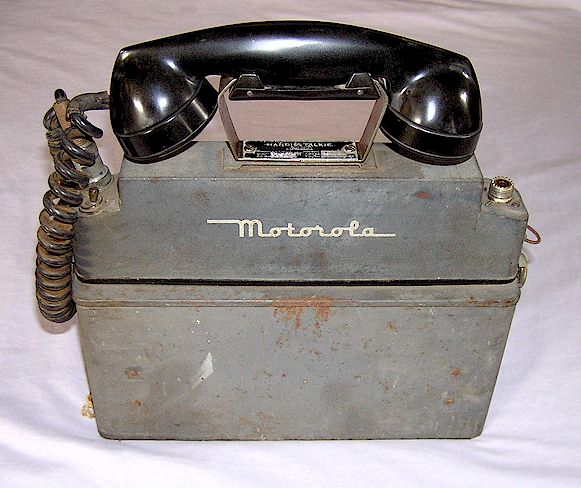
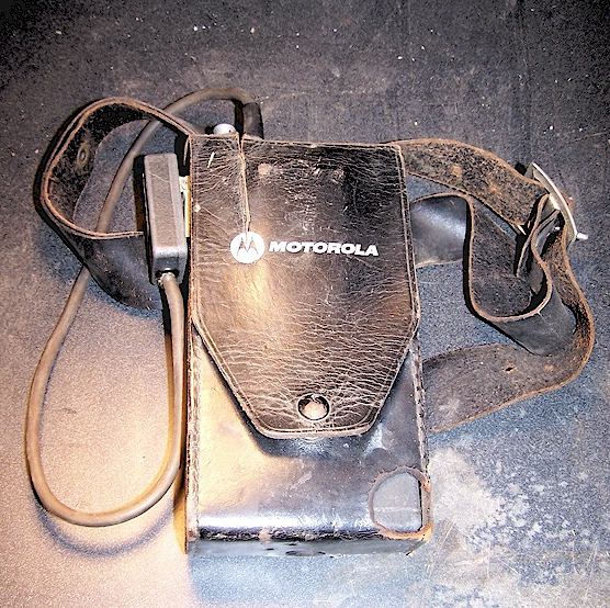
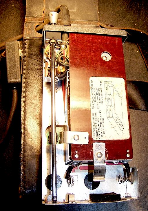
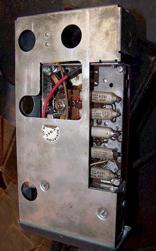
FHTR Series (1948 - 1956): The lower powered portables were the FHTR- series (FHTRU- for high band). They make use of subminiature wire-lead tubes in individual modules, and were powered either by a pair of 2 volt wet cell batteries with a vibrator power supply in a large battery box, or several 67.5 volt "B" batteries and a string of "D" flashlight cells in a smaller "dry battery" box. The FHTR series was available in one or two channel models, and could be ordered with extra transmitters or receivers inside for broad band operation. There was no speaker, only a handset which hung on a cradle across the top. Most handsets appear to have been supplied by Roanwell. There was no squelch in the receiver on most models, although it was an option, with the squelch control a screwdriver adjust potentiometer located inside the power supply.. Evidently the additional battery drain of the constant noise in the earpiece during no-signal conditions was offset by the savings in not using an additional tube and module for the squelch function. The FHTR- modules and basic design were incorporated into a custom made forest service semi-portable repeater station called a "lookout radio," which as the name implies, was used in forest service lookout towers throughout the country. This series appears to have been discontinued by 1956, although sometime around 1953 the model number was changed to H11-1 and H13-1.
Shown below is an FHTRU series pack set with the optional wet battery rechargeable power supply. Two clear plastic-cased 2 Volt wet batteries are inserted at each end of the power supply case, through panels in the bottom cover. A small vibrator power supply then provides the high voltage DC to the pack set.
These were also made for the military and numbered AN/PRC-23 and 24 (low and high band splits, appropriately.) (Thanks to Dennis Starks for this information.)
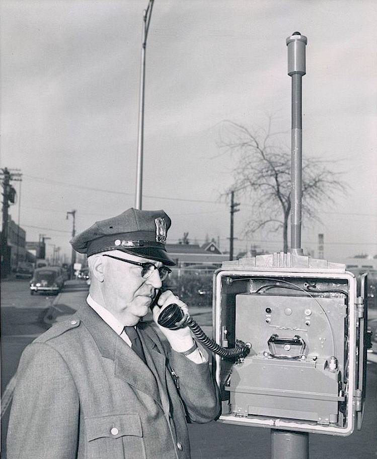
Unusual uses of Handie-Talkie Pack Sets:
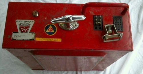
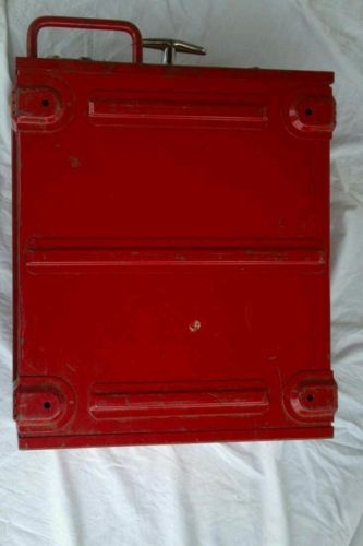
Shown below is a call box and emergency alerting alarm which used the above pack set, There appears to be an AC power supply in the box and some sort of alarm decoder that flashes a lamp on top of the pole. Oddly, it appears that there was no external antenna connected to the pack set, leading you to wonder what kind of range it would have had if the housing box was cast iron. It appears that the pack set could easily be removed and taken on foot if desired.
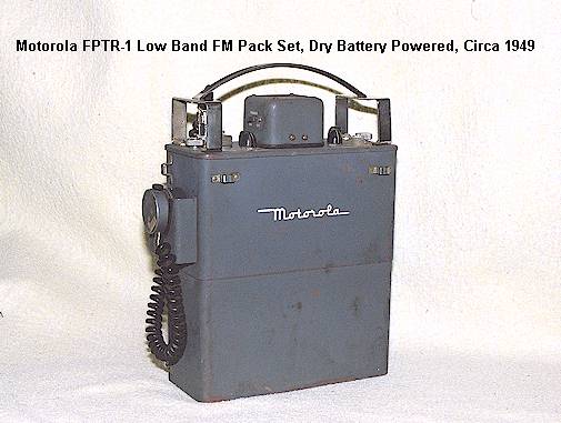
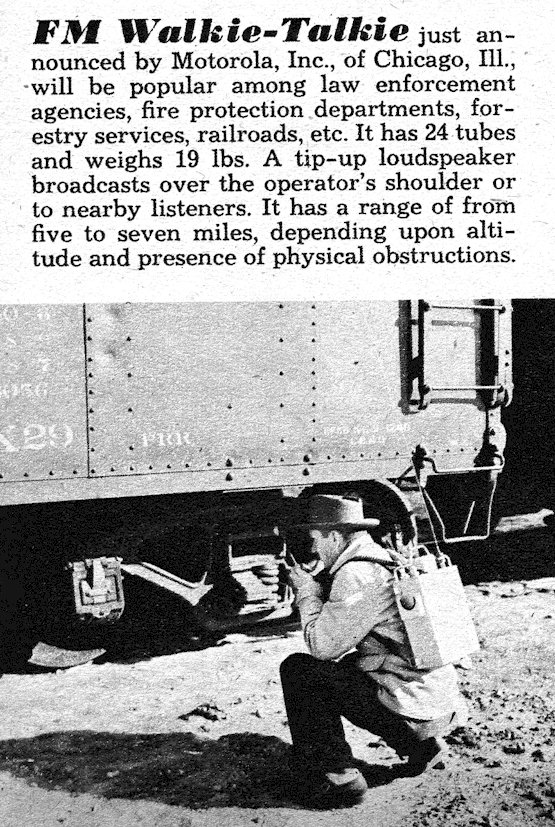
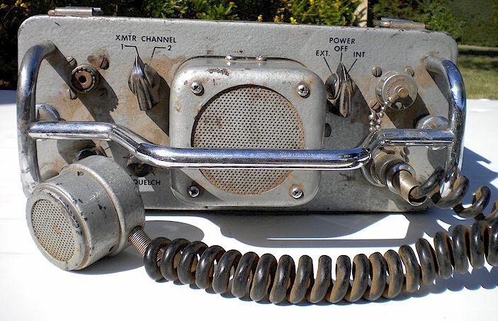
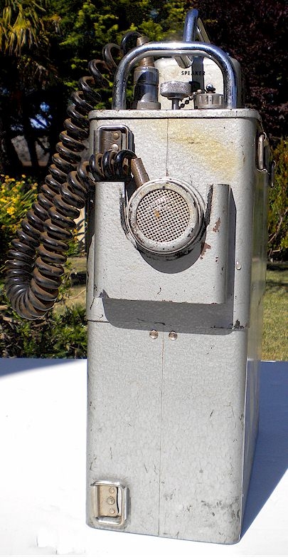
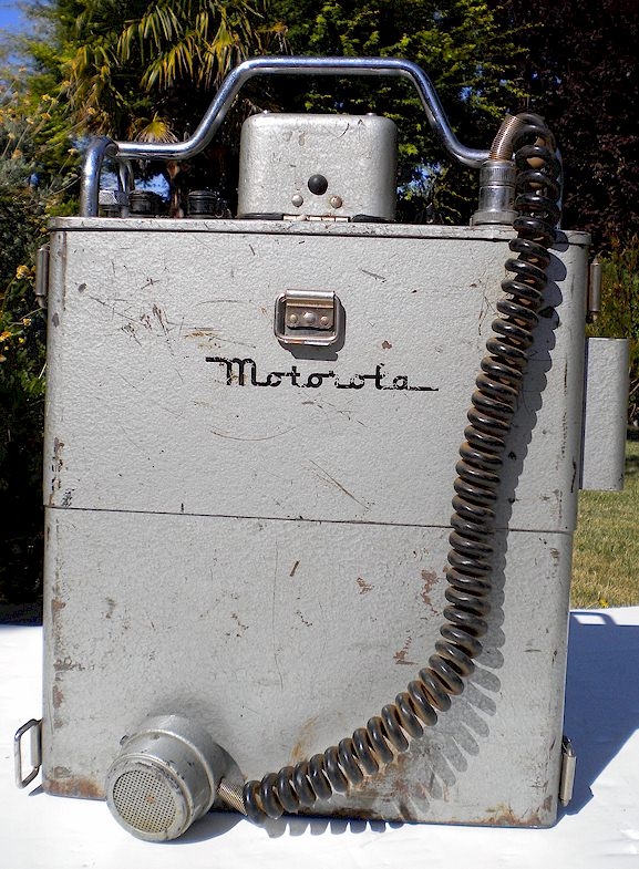
FPTR Series (1950-1957): The higher powered portables were the FPTR-series (FPTRU) in high band, and came in a much larger and different case than the FHTR- sets. They were introduced in 1950. The FPTR and FPTRU units had a large chrome handle across the top and offered a speaker/microphone combination rather than a handset, as well as room for multiple transmitters without increasing the overall original size (unlike the FHTR series which became quite a bit larger to accomplish the same thing.) They also offered squelch in the receiver as a standard feature, although that squelch was a relay-operated type rather than an electronic design. Like the FHTR units, there was a battery box across the bottom where large B batteries resided. The FPTR units use most of the same modules as the FHTR- sets. The FHTR equipment seems to have been discontinued at the introduction of the Research Line, but interestingly, the FPTR- equipment continued to be sold at least through 1956 after being re-numbered as the P11-1 (low band) or P13-1 (high band). Some are painted with gray wrinkle paint, while others are a silver-gray hammertone finish. I am not sure which is newer. An accessory AC-DC power supply was offered, which connects to the Cannon external power connector on the top panel of the equipment. Note that the microphone in the example below is a slightly later model; the one used with this model originally should be a round style made by Shure, rather than the Turner manufactured item shown here. I am not aware of a wet battery rechargeable power supply being offered for this model, as it was with the FHTR series shown above. These sets are surprisingly rare today compared to the FHTR style shown above.
Apparently the chrome handle was originally conceived to be a different shape. See the article below from the August, 1950 issue of Mechanix Illustrated:
Here's another set of photos from a summer, 2012 eBay auction
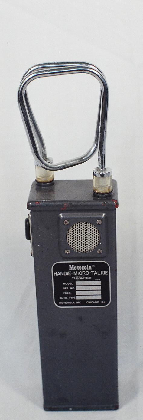
Handie-Micro Talkie: Perhaps one of the strangest and most obscure Motorola products of the 1950's was the Handie Micro Talkie, made with various model numbers and introduced in late 1953. The name is somewhat of a misnomer as this radio is actually only a portable transmitter, containing wire lead subminiature tubes, "B" batteries and the first use of the rigid loop "railroad" antenna which also doubled as a handle. In 1955 this antenna must have looked very "space age." They were used where it was only necessary to have a transmitter, such as in rail yards where a receiver feeding a PA system rebroadcast the signal from the Handie Micro Talkie over loudspeakers, or in logging where the same basic system was used. The housing is a sturdy metal one. The majority of these, if not all, were VHF high band in the 160 MHz range and the power level was about 50 milliwatts. A mid-1950's example was found carrying the model number number X13-1 and is shown below.
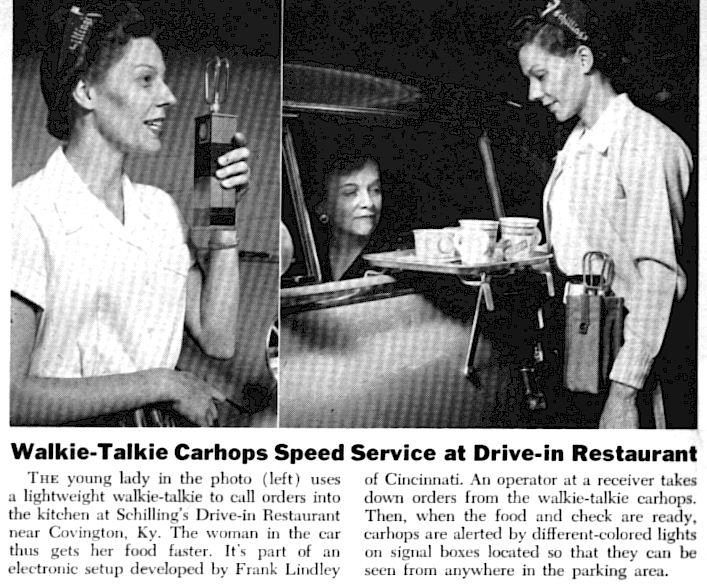
An interesting but apparently short-lived application for drive-in car hops is shown below, from the December, 1955 issue of Popular Science. Note that it mentions a system for communicating back to the car-hops but fails to mention that the Handie Micro-Talkie was only a transmitter, hence the need for signal lights in such a system. The Handie Micro Talkie was replaced in approximately 1961 by the all-transistorized pocket transmitter series H11NBC and H13NBC series, and to a limited extent by the H13NAC.(Z13NAC) portable transmitter, both shown below.
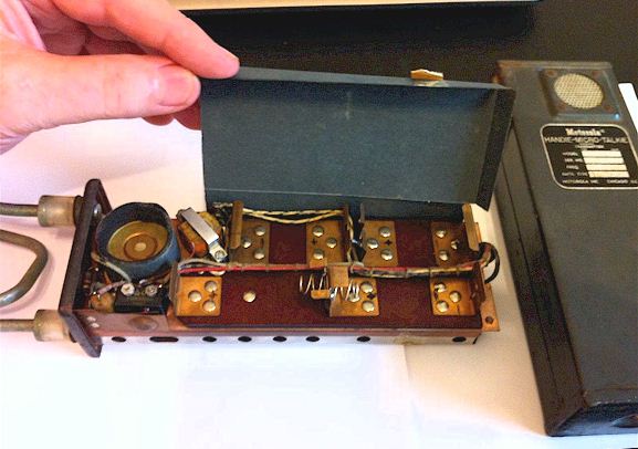
Inside the Handie Micro-Talkie:
MOTOROLA MODEL NUMBERING SYSTEM, 1942-54
(Deluxe, Handie Talkie, Dispatcher and Research)
Typical model numbers broken down, for complete sets:
"FMTRU- 30(D) " would be the model number of a complete set, as follows: F= FM equipment, M= Mobile, TR = transmitter and receiver, U = "UHF" (150-174 MHz), 30 = model series, D = dynamotor. The FMTRU-30D would usually consist of the FMRU-16V receiver and the FMTU-30D transmitter.
"FPTR-1" would be the model number of a "high power" speaker type pack set, low band, as shown above. The "H" as in FHTR-1 would refer to a low power handset model, as shown above. The letters mean: F= FM equipment, P= Pack set (H=Handie Talkie), TR=transmitter and receiver, 1= Model series. No suffix after the "R" means low band. A "U," as in FPTRU-1, would be a high band unit.
Further, "S" = Station, as in FSTR-80BY.
Individual unit model numbers would be as the following examples:
FMR-13V would be a low band FM receiver only, vibrator powered, 13 series, low band (no "U.")
FMT-30D would be a low band FM transmitter only, dynamotor powered, 30 watts
MOTOROLA MODEL NUMBERING SYSTEM, 1954-57
(Research, early Twin-V, Handie Talkie, Transistorized Dispatcher)
For some reason, Motorola briefly changed the model numbering scheme to a rather less informative one than used previously, during production of the "second generation: Research Line as discussed above, and this scheme only lasted a few years. It was as follows:
T43G-1 would represent a VHF high band 24 Watt mobile radio in 10" case. The "T" signified trunk mounting, the "4" being a 20-40 Watt power level, the "3" meaning 150-174 MHz band, the "G" representing "Unichannel" G series chassis "strips" inside, and the "-1" standing for whatever variation in that series the unit represented. Typical first letters could have been "H" for Handie Talkie or "P" for pack set, "D" for dash mounted radio, "M" for motorcycle, "R" for railroad, "X" and "Z" for special and industrial uses, "B" for base stations, "Y" for repeaters, "L" for desktop "Consolette" base stations, and a few others. An "A" suffix meant a wide-cased mobile using the "Sensicon" receiver and the larger "A" series transmitter.
Other models would have been deciphered as follows:
First (letter): D=Dash mount mobile, P=Pack set portable, H=Handie Talkie (smaller pack set,) R=Railroad, F=Fire engine version (rare,) W=Western Electric mobile phone, M=Motorcycle, S= Servicar three-wheeler. And a few others.
Second (digit): Power level. 1=Low power, to about 1 Watt. 2=Power to 2 Watts. 3= Power to 10 Watts. 4=Power to 25 Watts 5=Power to 50 Watts.
Third (digit): Frequency band. 1=Low band 30-50 MHz, 2=Mid Band 70 MHz, 3=High band 132-175 MHz, 4=UHF 400-470 MHz.
Fourth (letter): Type of strips inside. G series or A series, for example.
Fifth (digit): Combination of strips within that series, options included, etc.
It becomes obvious that this system is too limited in scope and as a result it only lasted a few years, replaced with the system used for the next forty years, which had numbers such as T43GGV-1100C, etc..
TWIN-V ERA, 1955-61:
MOBILES
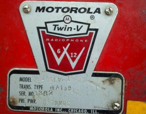
By late 1955, Motorola had begun production of an upgraded Research Line, called the Twin-V series, named so because of their ability to work in either 6 or 12 volt vehicles depending upon the selection of power and control cabling. The American auto industry had begun the switch to 12 volt batteries in 1956, and by that time practically all Motorola Research mobiles were 6 or 12 volt compatible. This was accomplished by split transformer primaries and dynamotors with dual windings.
Much of the Twin-V series differs little from the original Research Line, except for an expanded choice of optional receivers and transmitter power levels, and that all mobile models were capable of either 6 or 12 volt DC input. The transmitter and receiver strips from the Research Line were slightly upgraded to feature more modern tube types, but were otherwise variations of the same theme. The original Research Line mobiles, in the second generation type numbering scheme, continued to be made for a few years into the Twin-V era, probably simply to exhaust existing stock. The typical service manual, on the cover page, will use the words "Research Line" as well as "Twin-V" simultaneously.
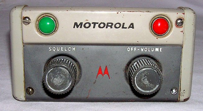
The original Twin-V control head appeared with the lamp lenses of the Research heads and was shipped with the last equipment still marked Research rather than Twin-V :
The "normal" most common Twin-V control head appeared as shown below, note the opaque plastic lamp lenses as opposed to the glass versions shown above.
Typical examples of the narrow and wide cased Twin-V mobiles are shown below.
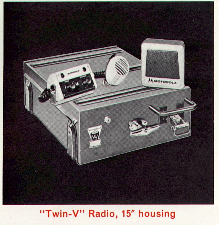
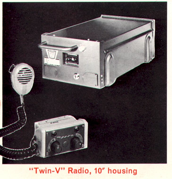
Note that in the above advertising photo from Motorola's Reconditioned Equipment Department, they have placed a Research series control head with the later "wrong" knobs on it, with a Twin-V mobile 10" drawer, apparently in an attempt to recycle everything and use up obsolete parts. The correct control head would have been the Twin-V style as shown on the 15" mobile above it (although they are electrically identical.) One of the former employees of the reconditioning department from that time has advised me that the radio drawers were separated from their accessories at trade-in time and all underwent reconditioning in separate operations, never to meet again.
By 1958, the Twin-V era equipment had begun to be replaced by the "T-Power" equipment, which was Motorola's last fully vacuum-tubed mobile. Twin-V equipment was still being sold from existing stocks until approximately 1962, although it is believed that full production actually ceased about 1959. The T-Power equipment will be discussed in Part Two and was still being sold in 1966. In 1959, Motorola also introduced the Motrac series, a completely new design with a fully solid state receiver and hybrid transmitter, which will also be covered in Part Two.
SPECIAL MODELS
Motorola always produced special versions of equipment in modest quantities for customers who could afford it. These included "Lookout" radios used in forestry towers, and special fire apparatus radios which were basically the same as the standard radios except for having a built-in high power audio amplifier to drive outside speakers on a fire engine (this was in the era before solid state siren amplifiers were developed to handle this purpose.)
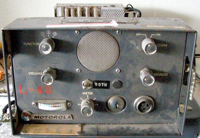
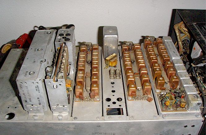
Shown below is a rare fire apparatus Twin-V radio, an F43GGV series unit. Normally this would fit in an 11" case, but because of the accessory audio amplifier, it required the 15" housing. Interestingly, it was painted red rather than gray. Photo from an eBay listing. Note the case is on upside-down!
Shown below is a February, 1958 dated forestry lookout radio which is made from Transistorized Dispatcher radio strips inside a modified 11" Twin-V housing.
Other special models included locomotive radios, marine equipment, mobile telephone service equipment, industrial signaling alarms, and so on.
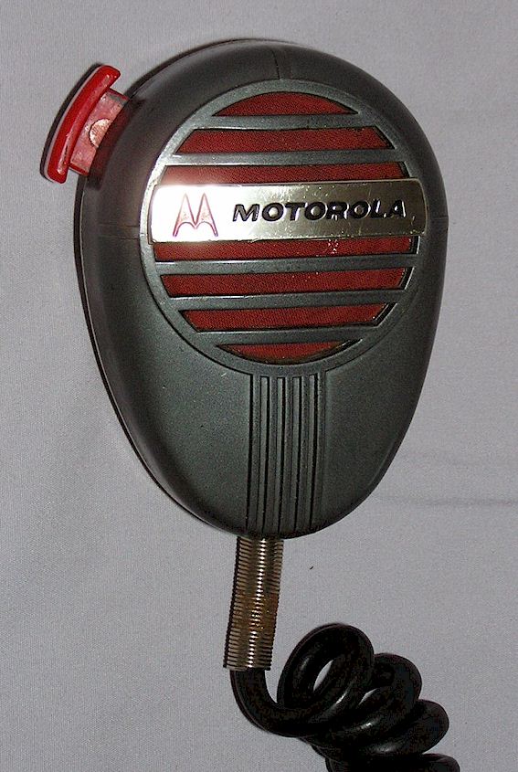
SPEAKER MIKES!
For some reason, during the Twin-V era, Motorola offered a normal-appearing mobile microphone which was actually a speaker-microphone. Instead of the usual carbon cartridge of the time, a small paper-coned speaker element and transistor amplifier was placed inside the microphone. The speaker-microphones can be recognized by the front section being a dark gray color with the rear half a flesh-tone color, while the standard microphones are the opposite color scheme.
Transistorized Dispatcher Series (1957)
Probably the most long lived as well as successful series ever made by Motorola was the Transistorized Dispatcher radio. Introduced in 1957 with sales beginning in 1958, these have also been called "Industrial Dispatcher." The name is somewhat misleading as these had plenty of tubes in them. The receivers were almost all transistorized other than two wire-lead subminiature tubes, however in 1962 the second generation of these was introduced which had a fully transistorized receiver. Because this series is covered rather extensively in my motorcycle and CHP Radio pages, the data is not reproduced here. Instead, check these pages for information on this model:
CHP Radio pages on the Transistorized Dispatcher
"TRANSISTORIZED DISPATCHER" PORTABLES (Post 1958)
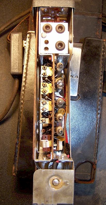
The venerable pack set FPTR series (briefly re-numbered P11- and P13-) were replaced in early 1957 by the partially solid state "Transistorized Dispatcher" chassis pack sets. Motorola never referred to these pack sets as "Transistorized Dispatcher" but the chassis sections within were what was used on the new motorcycle and industrial radios. Instead, the tag says "Handie Talkie FM Radiophone." The first generation receivers were fully solid state other than two subminiature tubes in the IF section. The transmitter was primarily subminiature tubes (1AD4) with subminiature 6397 driver tubes for the high band version. The low power versions ended with a 3B4 (low band) or three 6397's (high band) power amplifier. For the first time, power levels were 1 Watt for the low power set and 5 Watts for the high power. All high power sets used a 2E24 tube as the PA tube. The 2E24 is an instant-heating version of the 2E26. All tubes in these sets were instant-heating, which in reality meant that the operator would depress the push-to-talk switch and then wait approximately one second for the tubes to heat, before speaking. These pack sets were available in three main power configurations - - dry batteries, nicad battery with built-in charger, or AC power (portable base station.) The transistors were Germanium types and the circuit boards were an early generation phenolic type with thick traces.
Something strange is that for the high band models with the AAC suffix, there were at least -SP and models with a "Z" prefix typically had a high IF crystal controlled oscillator at 12.455 MHz and were also fully solid state. These models required their own special battery packs and were marked with the schematic symbol of a transistor screened onto the top edge of the control panel and also on the side of the power supply. In other words, there were two crystals on the receiver board. On the later BAC suffix radios, which were also fully solid state, there is only one crystal, the frequency determining one, and that acts as the mixer frequency as well, which is known as a "derived IF." In other words, the circuitry is vastly different between "BAC" models and the earlier Z23AAC and H23AAC models with the transistor logo screened on them.
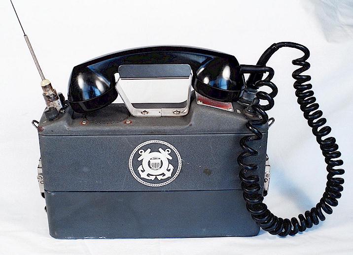
The center section is the transmitter-receiver chassis area, the bottom section is the battery or power supply, and the top section holds only the speaker and controls. These were also available in a handset model, and continued to be made through about 1966 with various refinements, such as the receiver finally becoming fully solid state. A special model for the US Coast Guard was made which had both a handset as well as the speaker, in contrast to the standard handset model which deleted the speaker.
They were purchased in large numbers by forestry agencies, fire departments, civil defense and the military. They are very reliable and reasonably easy to work on, the chassis sections folding out like the pages of a book for service. The transistors are all metal cased early Germanium types, and the boards are positive ground. In the nicad-DC models, the power supply is a DC-DC converter so that the output is isolated and unrelated to the input, thus placing the case in contact with the grounded metal body of a 12 Volt negative ground vehicle will have no effect.
Typical early numbering of these at the end of the second generation Research era (early 1957) would be H21-1 or P33-1, although since the majority of these pack sets were manufactured during the Twin-V era and later, the numbering would typically be H21AAC-1100 or H23AAC-1100, for example. I am not sure whether a Ni-Cad powered rechargeable was ever made for the -AAC series models.
A few of these sets were available as special orders with multiple transmitters or multiple receivers for broadband operation. Quantities of these radios were leased to the U.S. government during the early years of the Vietnam conflict, and delivered to Saigon, where Motorola maintained a service depot near the airport. The government of the Republic of Vietnam also purchased quantities of these radios, as did the now defunct government of 1950's Cuba.
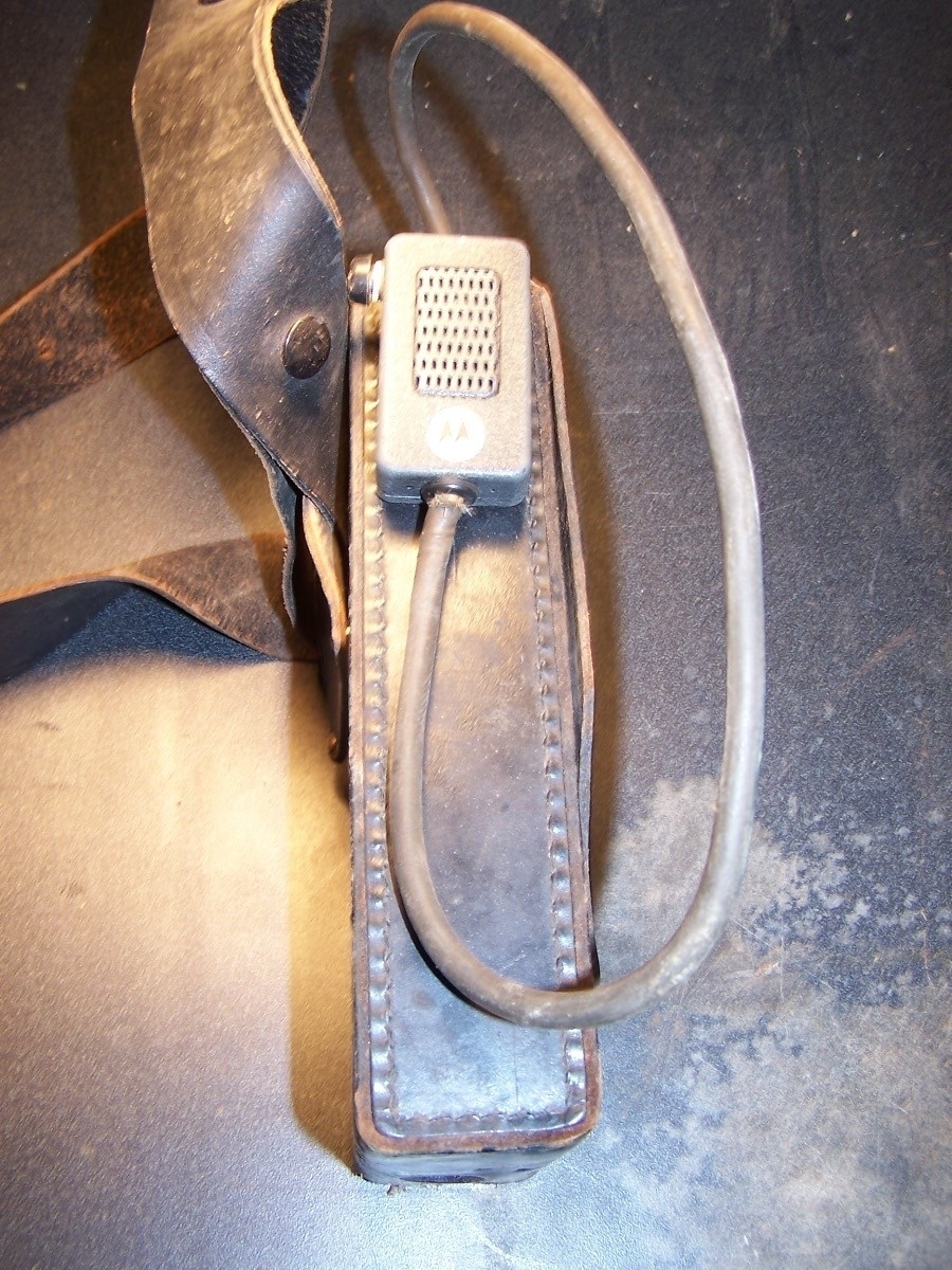
Shown below is a high power (5 Watt) VHF high band pack set, and a low power )1 Watt) VHF low band pack set. Both with ni-cad power supplies. The dry battery power supplies on these models are recognizable by the lack of a hinged door on the side of the power supply (where the charging and external power cables connect.)
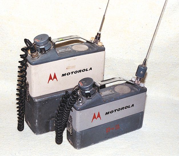
Photo below is of an interesting military contract version of the "Handie Talkie" pack set radios. It was assigned the AN/PRC-58 number, but it is basically the H23AAC-1100 high band set with the change that a handset is featured and the on/off switch is a rubber covered toggle rather than the round turn-style which would shut off when the handset was returned to the cradle. Note that the stock Motorola H23AAC-1100 handset model did not have a speaker and had a smaller-height battery box. Note also that these portables really belong in Part 2 of this series, in that most of them were made after 1958. The military model below was made in approximately 1960. The version for the army and navy was numbered AN/PRC-61 (Thanks to Dennis Starks for these numbers!)
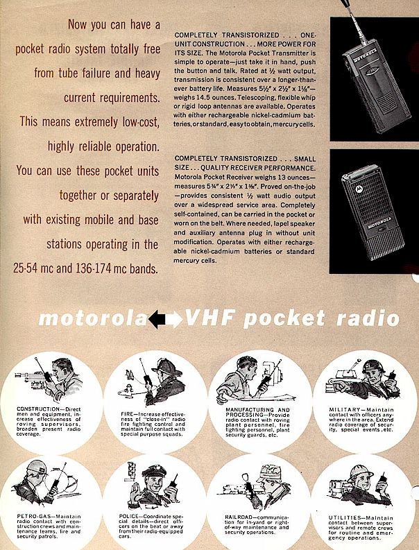
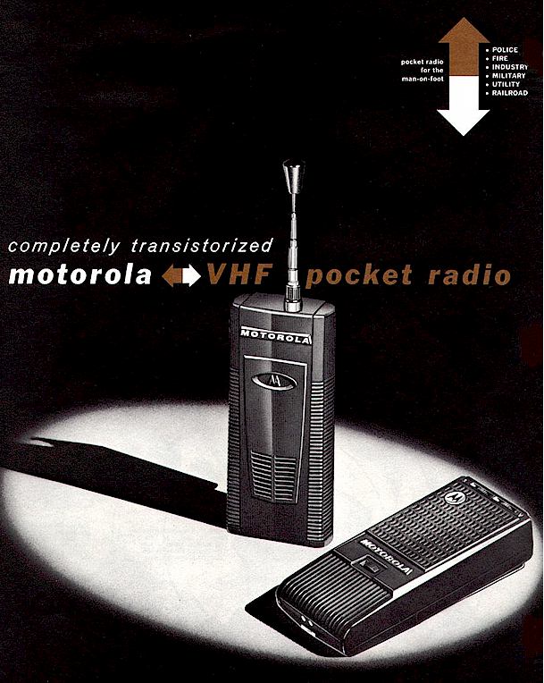
Pocket Radios
The first attempt at a truly solid state portable radio was the set of "pocket radios." These were especially strange as the receiver and transmitter are two separate units, although this allowed the receiver to be sold separately and also used as a pager rather than a straight radio receiver. The receivers were always fully solid state while an initial model of the transmitter was hybrid. These units began to show up around late 1960 and appear to have been made through about 1964. There is a muting circuit in the receiver which mutes it in the presence of strong RF, such as when the transmitter is on the air. These were not popular and they are very rare today. The receivers, available in low or high band, carried numbers such as H01ANC (low band) or H03ANC (high band.) One reason they are rare today is that the plastic used in the housings became brittle with age if stored in hot locations and would easily shatter into many pieces with some provocation! The power level of the transmitter was less than 1 Watt, mercury batteries (non-rechargeable) were usually used although a set of Nickel-Cadmium batteries was available along with a drop-in charger.
Shown below is the last version with fully solid state transmitter, models H11NBC (low band) and H13NBC (high band.)
Shown below is an older transmitter, which was primarily vacuum tube and dates from about 1958-1959. It is an upgrade of the earlier "Handie Micro Talkie" shown earlier on these pages. Few were made. A careful look reveals that it is simply the exciter and PA driver sections from a Transistorized Dispatcher series motorcycle radio or pack set, placed in its own case with a set of mercury and high voltage dry batteries. These were typically model H13NAC (high band) or H11NAC (low band) although a number with a "Z" prefix were made for the federal government for use by military personnel. At the time this was offered, there was apparently no matching receiver available. These were used mainly for remote access of a PA system in rail yards and crane structures. It is believed that the main difference between this and the "Handie Micro Talkie" is that this provided somewhat more power and longer battery life, and had the smaller remote microphone capability. These were sometimes also used in law enforcement for concealed use and later, sometimes with the pocket receiver above when those came on the market.
Narrow Band conversions:
In 1962, the FCC required that all VHF low and high band systems be "split channel," i.e. the maximum frequency deviation of the transmitter was limited to 5 kHz and channel spacing was reduced from 60 to 30 kHz. A great deal of the equipment still in service from the 1950's was retired at this time rather than being converted to narrow band, especially since American cars had changed to 12 Volts in 1956. The cost to convert an older radio to both 12 Volt operation and narrow band was often more than the equipment was worth by then. The availability of partially transistorized equipment further eroded the interest in keeping any of this older equipment, such that much of it was gone by the early 1960's.
Equipment which was converted to narrow band using kits supplied by Motorola should display a silver sticker or nameplate with the letters "CC" followed by the new type acceptance number for a narrow banded radio. Equipment so marked shows up every once in awhile today.
This page created by Geoff Fors, Monterey California. Copyright 2000, all rights reserved.
Ver. 07/27/2022