
U.S. Forest Service
Type SPF Radio Set
Supplemental notes...
PLEASE NOTE:
This web page is a bit unusual in that it is intended as a supplement to the article in the November, 2010 issue of Electric Radio Magazine regarding the U.S. Forest Service Type SPF portable HF transmitter/receiver radio set, and is not all-inclusive by itself. If you do not have that article, it is suggested that you obtain a back issue from the publisher, at:
https://www.ermag.com/index.cfm?v_link=back_issues&v_product_type_name=Back Issues
That article covers the history in great detail and as long as that back issue is available there seems no need to reproduce the same data here. However, as time goes by I will be adding more material as that article ages and becomes harder to obtain, and may include my own version of the material in the article.
HISTORY
The SPF was developed by the US Forest Service in 1935 and produced in various models through at least 1940. It was a method of providing communications over a 20-50 mile range back to a fixed base (as opposed to other portable setups) in the 3.4 MHz range, AM voice or CW at about 2 Watts power. The original, first generation SPF was made in a quantity of 200 units and was rather different than all the other models that followed in that it used the early tubes such as the Type 19 and a rotary send-receive switch rather than the lever type of the later models. They were made in assorted models, beginning with the original SPF and going through such models as the AA, AB, etc. through AF and were mainly made by Radio Specialty Mfg. Co. in Portland, Oregon although some were apparently produced by Pacific Electronics. The final version was the Type AF, circa 1940, and was apparently only made by Spokane Radio Co. in Spokane, Washington, and most of those were produced for the United States Army Signal Corps and actually delivered in 1943. Unlike the other SPF's, the AF has a conventional Cinch-Jones power connector instead of the strange proprietary style shown below.
By the mid 1940's the basic SPF design had also been made by other manufacturers including Marconi Canada and Success Radio Service of Salt Lake City, and there are most likely half a dozen others.
Each model SPF (such as AA, AE etc.) was produced in the quantity of approximately 200 units. The total production of the SPF was approximately 1200 units (thanks to Rick Ferranti, W6NIR for this data.) This does not include the sets made by other makers and countries which were not actually labeled "Type SPF."
The SPF sets were still in use into the late 1950's although by 1947 the US Forest Service as well as state forestry agencies had begun to transition to VHF FM equipment in the 30 MHz band, where line of sight signal propagation was proving more reliable and predictable, and after that into the 170 MHz range.. Many SPF's were simply hauled to the dump during those years, sadly.
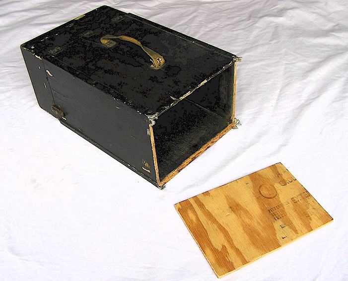
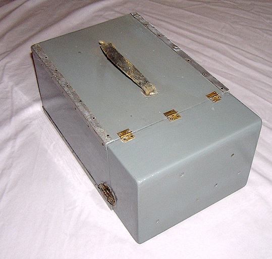
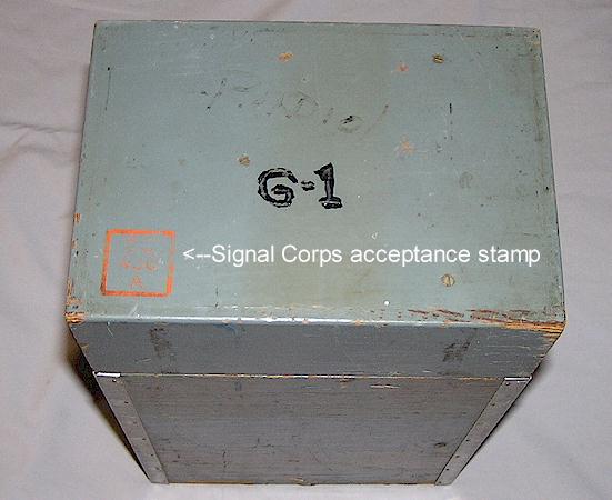
The Kit Box
Originally the SPF was stored in a wooden box called the "kit box," which would have contained the SPF itself and the accessories such as the batteries, antenna and so forth, at least where it was intended to pack the SPF in on a mule or a truck. Smoke jumpers and hand crews headed into the wilderness would typically have had one man packing the SPF and another the batteries and accessories, and in that case there were canvas cases for the SPF and the smaller separate kit box, which contained the batteries, antenna and odd accessories.
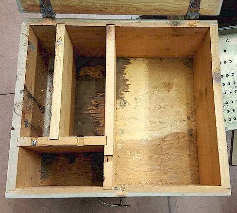
Photo courtesy Hue Miller, K7HUE
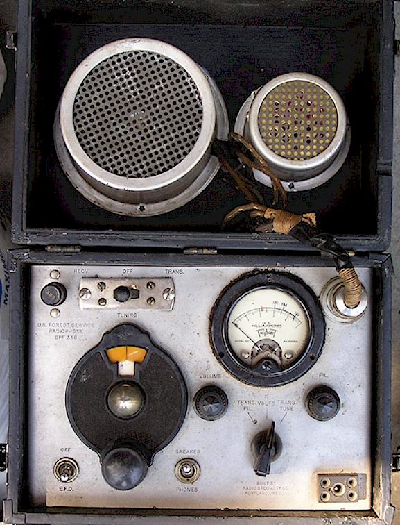
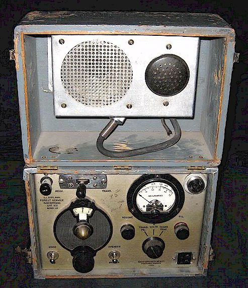
A typical early SPF set and its restoration:
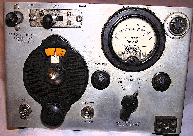
Note the ballast tube socket remains, but no ballast tube should be used where GT Octal tubes are employed, and it is left empty. If you get one of these, don't be fooled by the empty socket! The socket lugs are still used as tie points. See explanation in "Common Issues" below.
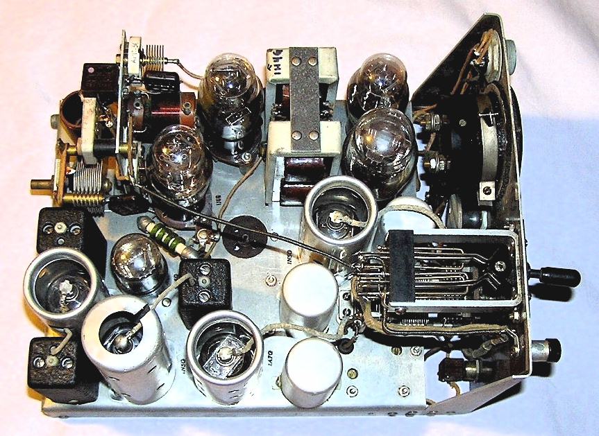
Common Issues and a Typical Restoration:
The service manuals are divided by serial number ranges and suffix type. Originally this was no problem but during the war years and probably after, earlier sets were upgraded and modified to meet the later designs. Principally this means that the tubes were changed to the smaller and more modern octal 1.5 and 3 volt types, and as a result the ballast tube was removed and not used. In addition, the tap on the under-chassis bias battery was also no longer used. Because the ballast tube socket remains, some people have thought that the tube was missing, and should be replaced, but note that the socket was retained only as a tie point for wiring. Interestingly, even in the later models which came from the factory with the GT octal battery tubes, the ballast tube socket remains, but is riveted to the bottom of the chassis without any hole being punched for it! Therefore you should check the circuitry carefully to see which version you have, regardless of serial number, as the set may have been upgraded, such as my example shown above. Upgraded sets generally match the Type AF model (made by Spokane Radio mainly for the military during the war) other than the power connector, which remained the strange proprietary US Forest Service female socket rather than the common Cinch-Jones type of the AF sets. Some upgraded sets have the new tube type numbers inked on the chassis, but most seem not to.
Others have reported that open windings on any of the set of transformers are not unheard of. Check these when troubleshooting.
Note that the correct original crystal should be more or less in the 2.6 - 3.4 MHz range. Anything far above or below that is not correct, and not original.
The bias battery can be made by soldering three AA batteries together in series, wrapping in plastic sheeting and then in a cardboard sleeve. A hot glue gun helps. The purpose of the plastic and cardboard being mainly to protect the set from the inevitable and eventual leakage of the batteries. It's probably better to use regular carbon-zinc cells as sold by the Dollar stores as "Heavy Duty" rather than "alkaline," as alkaline seems to be more corrosive and more likely to erupt later and make a mess. Once upon a time there were AA batteries called "photo" batteries, apparently better sealed so as not to ruin your camera gear, but I haven't seen such marked batteries in ages.
Field changes to early model USFS SPF sets were:
Changed to use later GT style 3 Volt and 1 Volt tubes and ballast tube eliminated.
Before New
1F5G
3Q5GT Total filament current reduced from 360 to 300 ma.
1D7G 1N7GT
Original tubes are 60 ma filament current each, new ones are 50 ma
1D5G 1N5GT
• Filaments rewired to conform to AF series wiring
• 0.1 Mfd bypass capacitors added to filament line as on AF models
• Ballast tube removed and not used (but socket remains!)
• Bias battery tap unused - - only 4.5V used now, per AF schematic
Antenna:
The original antenna was a Windom with single wire feed and no ground. This provided NVIS propagation out to 20-30 miles under normal conditions and sometimes 100+ miles at night. An SO-239 connector on the front panel would NOT be correct, so please don't add one, and adding a ground to the set will affect the radiation angle to some extent but might be beneficial for making longer distance contacts. The Pi-Network output stage was intended to match the Windom style antenna and I do not know how far outside that match the set is capable of accommodating. I am guessing the original Windom probably presented the set with something in the range of 200 Ohms, slightly capacitive. Correspondence with people who have tried other antennas is welcomed.
Rebuilding Parts:
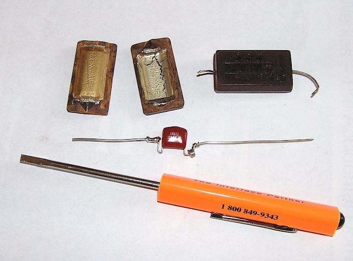
The SPF is full of a variety of capacitors, as if they were bought in whatever form was available at the moment or what was the cheapest. Of the paper style, there are wax coated cardboard tubulars, a "fake" bathtub style next to the bias battery, and several molded Bakelite types (Micamold = Boo!) . They will all be bad. I sawed open the Bakelite types with a Dremel rotary tool with cut-off blade, scraped out the innards, refilled them with a modern dipped plastic style and glued them back together with a hot glue gun. See below for an example. I like the thick leads of the original style which is why I patched them on to the modern capacitors with their thin ones. The tubular wax styles were re-cored by heating with a heat gun and pulling out the innards, then refilling with a modern axial lead type and plugging the ends with molten wax or hot glue. The bathtub assembly was removed from the chassis, where it was found that it was not hermetically sealed at all, but just had a plop of black tar covering a generic wax paper tubular capacitor assembly. Again, the heat gun removed this mess and modern poly capacitors such as shown below were placed inside, and the assembly re-mounted on the chassis. Check all the resistors with a digital VOM. You are looking for any more than 10% high in value. It is not necessary to disconnect a lead to test them. Oh, and a lot of people seem clueless as to how to measure paper capacitors for good-bad. Measuring the value of capacity is almost meaningless. You want to measure the leakage at rated voltage. Not the value. Modern capacitance meters and so on are useless. Use a 1950's bridge with leakage measurement such as a Sprague, Heath or Eico. But as I say, they will all be bad anyway.
The bakelite type re-stuffing:
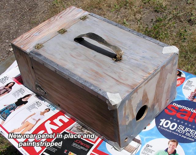
Deteriorated Cabinets:
The cabinet on my example was missing the rear panel, perhaps it had been dropped or somehow damaged. I made a new one out of a sheet of 1/4 inch plywood. The paint was also an awful slopped-on black mess, so I had to strip it and repaint it, which required endless wet sanding and so forth. The original finish was a flat gray, without wood grain showing. I had a devil of a time getting something close to this but after many brush coats of a thick gray enamel followed by sanding between coats, I got a pretty good result. I now realize that I should have coated the wood with a sealer such as Kilz before painting the gray, so that it would not have soaked in so much, saving me a lot of time.
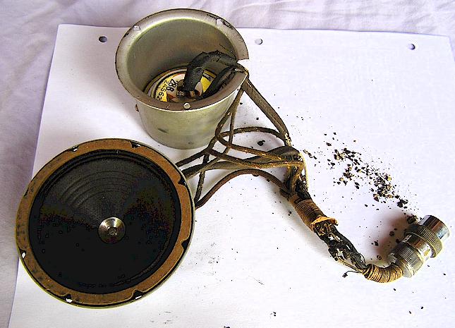
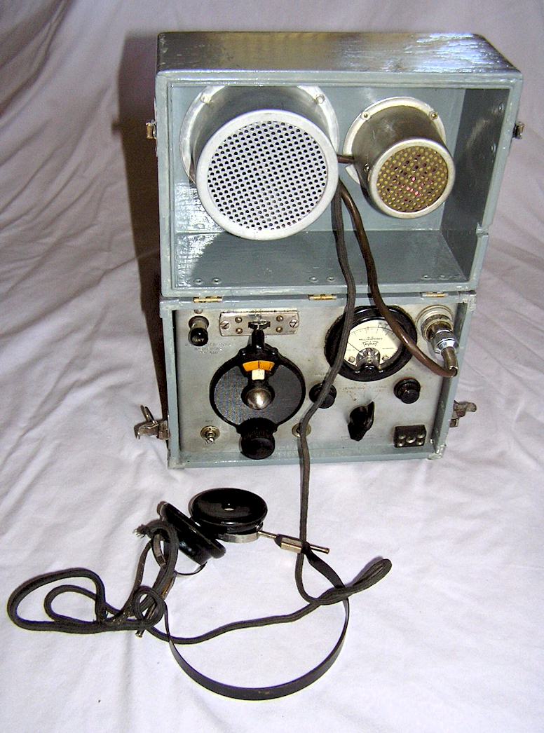
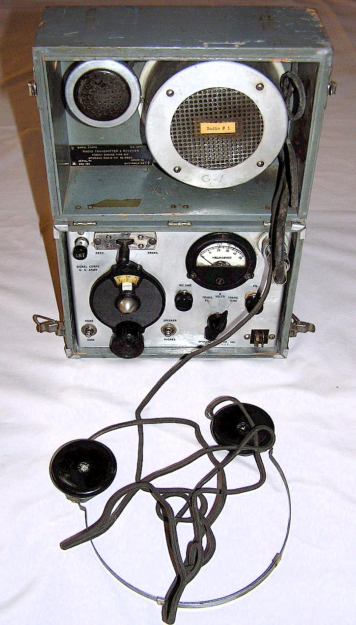
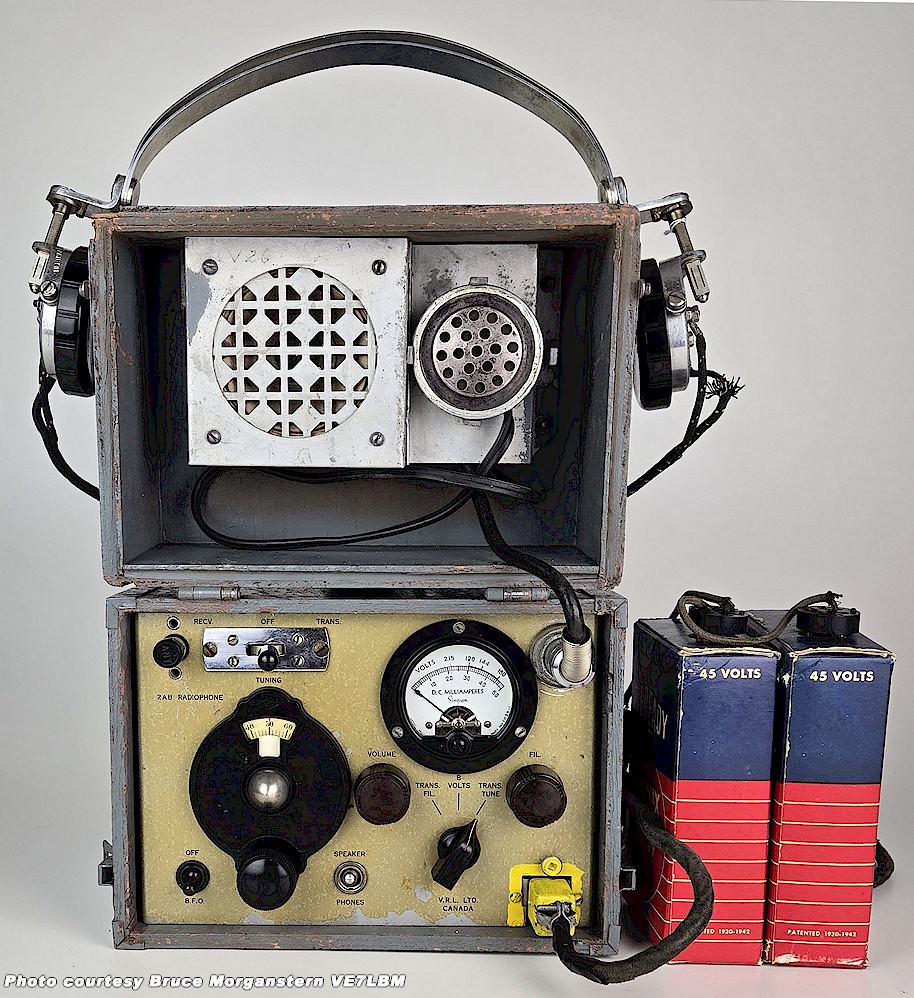
Note the round separate housings for microphone and speaker in this model. The microphone does not detach and is built into the lid. The headphones were missing when this unit was found. The originals in the early SPF's were Trimm Featherweight type usually marked "US Forest Service." Mine was missing the headphones when I got it but through the kindness of a fellow ham I was given the correct set. Not many versions of early magnetic headphones will fit. They are stored looped around the speaker assembly in this style and the headband has to be fairly springy and flexible. The early speaker as shown below is a magnetic type with a fairly high impedance voice coil. Not 8 Ohms ! The speaker in the last models, the AF's, is a standard PM style.
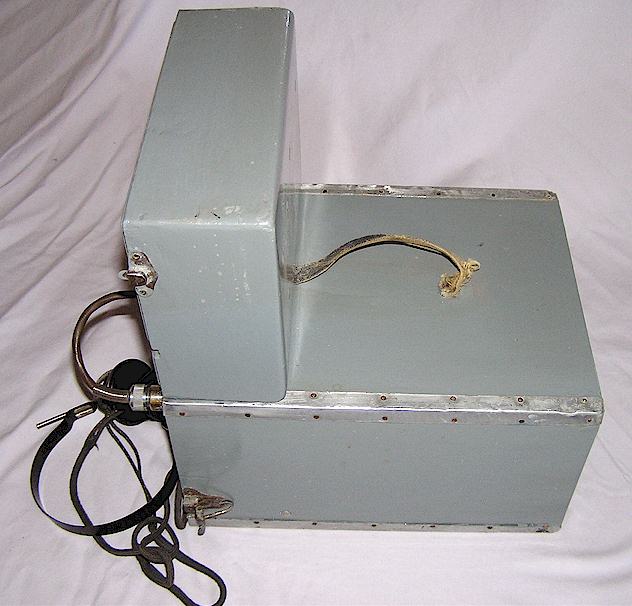
As found:
Following restoration, handle has since been replaced:
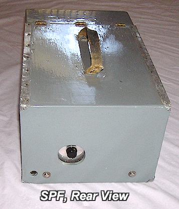
Connectors:
The power connector on the models before AF is a strange proprietary type which you are never likely to find, as seen above. It was made by the Howard B. Jones Company in the 1930's and is also found on some Zenith entertainment console radios of the same era (not that this helps us now.) The Jones Company would eventually become the Cinch-Jones Co., a major maker of inexpensive multi-pin connectors, probably at the same time this series was discontinued. The best solution is to use some short banana pins for each hole. My plan is to take a piece of thin Lexan plastic and drill it to accept short banana style pins robbed from some military connector in the junkbox, and then pot the assembly in clear epoxy after the wires have been soldered. Or possibly pot the assembly with black RTV. The speaker-microphone connector is an odd early variation of the standard Amphenol microphone connector used on two-way radios for decades. The odd part is that there is no keyway notch in the socket shell and it is possible to insert the connector any of four ways! I solved this by putting a dot of red paint on the male shell and the female socket pin area to index the right way. It would probably be better to replace them with the newer keyway version connectors but I decided to keep this one original. I later saw other SPF's which indeed had the remains of paint dots from the factory.
Power Requirements:
Originally the SPF expected you to provide, via batteries, 3 Volts (A,) 135 Volts (B # 1) and 180 Volts (B # 2, Transmitter.) If you make an AC power supply or use your own DC-DC converter design, the manual quotes the following current requirements:
Battery Transmit Phone Transmit CW Receiver
A (Filaments) 700 ma (!) 320 ma 150 ma
B (135 V) 10 ma 0 ma 6.5 ma
B (180 V) 60 ma 35 ma 8 ma
The heavy duty filament voltage ( 3 Volts) consists of eight # 6 ignition cells (last seen in high school in the 70's.)
The B batteries are four # 115 45V B batteries in a series-parallel arrangement.
The exact battery arrangement is shown in the manuals.
Frequency Coverage:
The transmitter should have enough range to make it to the middle of the 75 Meter band, it just depends upon the crystal used. The receiver, on the other hand, seems barely able to make it to the first 25 kHz of the 80 Meter CW allocation, i.e. 3525 kHz, if that, and is specified in the manual as ending well below 3500 kHz. Since this set is intended for AM operation as well as CW, it's no fun not being able to use it. My plan is to add series capacitors to the receiver variable capacitor assembly to reduce the capacity of each section so that the receiver then tunes 3.5-4 MHz. Stay tuned for how this works out, or write me if you have done this already. The manual states that the receiver frequency coverage is nominally 2900-3525 kHz.
Manuals Available From Me:
So far I have scanned the US Forest Service Communications Handbook, which includes operating instructions for this and all other USFS radios and telephones in use through 1955 (but not schematics or service data.) This is thanks to the courtesy of Hue Miller, K7HUE of Oregon who generously loaned his copy for scanning. Rather than put a pdf copy here for direct download, which encourages leeches and bandwidth hot-link vultures to attack my server, just send me a note and I can E-mail it to you. It's an 8 Mb pdf file. This handbook does not contain schematics or technical details of the radio gear itself, just how it was used and hooked up.
There are several versions of manual for the SPF. The Signal Corps produced a manual for the AF. There were also individual US Forest Service manuals for the SPF AA-AE versions, and there was also at least one "master" handbook which has the schematics for virtually all US Forest Service radio gear at the time of publication (I do not have that one yet. Please share if you do!)
UPDATE: I have now scanned the manuals for the SPF Models AA+AB and AF. The AF is the Signal Corps model with the Cinch-Jones connector on the front for power, marked "Signal Corps." I will be putting these up for direct download soon but in the meantime, E-mail me if you want a copy by return E-mail. Be aware that the SPF-AF manual is about 8 Megs and your mailbox has to support files of that size. The AA+AB, I have made in two parts of about 4.7 Megs each to make it easier to fit into mailboxes such as Yahoo and Hotmail.
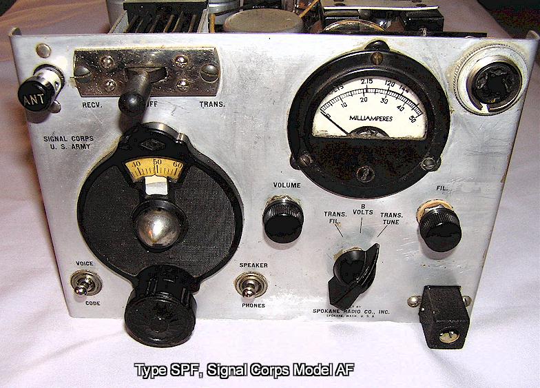
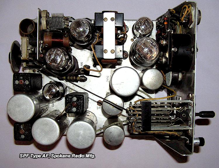
THE SIGNAL CORPS MODEL AF, Spokane Radio
The photos below show the Type AF model SPF, this one by Spokane Radio, which was supplied to the US Army Signal Corps in 1943 and was the last US Forest Service model. Note the lack of the ballast tube socket and that there is an alligator clip allowing disconnection of the B+ line to the PA tube (neutralization routine.) Note also the Signal Corps logo on the panel. The serial number now appears on the wooden box inside, on an engraved plate, rather than the front panel of the set. The carbon microphone has a snap button on the rear and can be detached from the round wooden mounting post that holds it and held as a traditional microphone, an improvement over the earlier models. The power connector on the AF is a common Cinch-Jones style, gone is the earlier Howard B. Jones / Radio Specialty connector used on the earlier sets. The front panel of this SPF model says "Signal Corps" at the upper left while the models supplied to the Forest Service still say "Forest Service Type AF."
The AF series was manufactured by at least Radio Specialty Mfg. Co., Spokane Radio, and Pacific Electronics. It is unknown whether the Spokane Radio models were ever made for the Forest Service or if all were intended for the Signal Corps and so marked. There were also "clones" made for state forestry agencies as well as a Canadian Marconi version for use by Canadian forestry agencies, none of which were marked "AF."
One strange thing - - when I acquired this Type SF in 1978 from a fellow scrounger, it was part of a lot of some half dozen of them, and they all featured large plastic stickers on the exterior which said "US Department of Health, Education and Welfare." Why, I have no idea,
l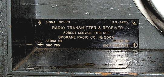
OTHER SPF SETS, CLONES ETC., AS SEEN ON EBAY OR AS OWNED BY OTHERS:
The SPF sets were used not only by the US Forest Service but by other state and federal agencies as well. Some examples of those are shown below. The SPF was also adopted by the US Grazing Service after the CCC was disbanded and thus ceased providing manpower when WWII began for the United States. Those sets bear a "Grazing Service" ID tag rather than a forestry one.
MODEL AB SPF, 1100 serial range:
This is an early set, Type AB. Note that the speaker and microphone have been combined in a single box in the lid in this case, but the headphones .have been pillaged and should otherwise be there. The power connector has been changed somewhere along its life to the style used on the AF series, except backwards polarity.
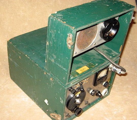
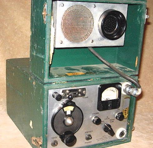
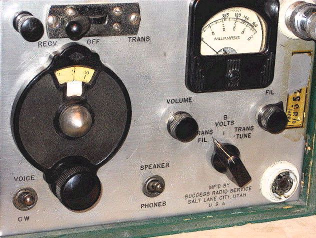
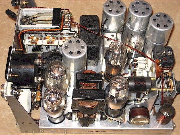
SPF MANUFACTURED BY SUCCESS RADIO SERVICE, SALT LAKE CITY:
Note different power connector style. This model was manufactured for and used by a state forestry department rather than the US Dept. of Agriculture. Note that as in the above example, the headphones have again been pillaged. It is unknown whether the color was always green. This model makes used of a ballast tube as the early Radio Specialty sets did, along with the ST bulb tubes (which require the ballast, unlike the octal tubes of the later designs.)
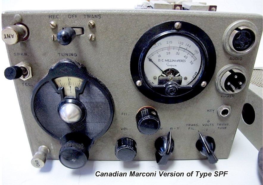
CANADIAN MARCONI VERSION of SPF:
This version showed up on eBay circa 2016, showing that the Canadians also had copies of the SPF. Note the different front panel layout .
CANADIAN VANCOUVER RADIO LABORATORIES TYPE 2AB Version
Yet another Canadian version.
CALIFORNIA DIV. OF FORESTRY MARKED SPF
This is an SPF Type AE which was used by the California Division of Forestry, the agency which traditionally managed state parks and was responsible for fire suppression in unincorporated areas of the state.
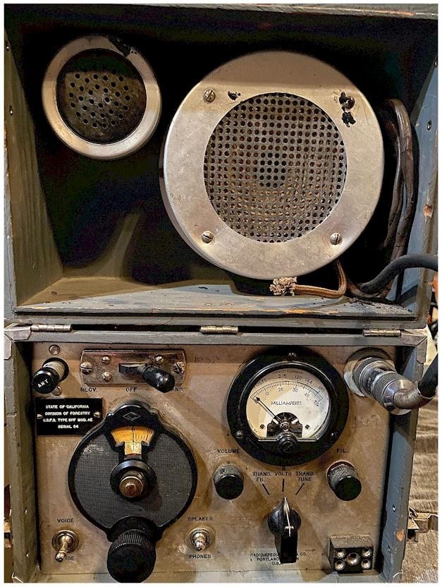
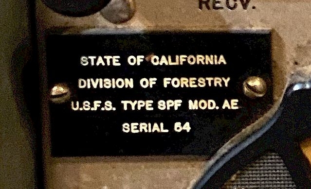
Thanks to Jarrod Stranahan, KN6PKE, for the above two photos
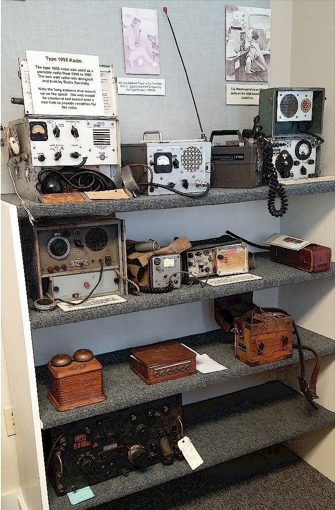
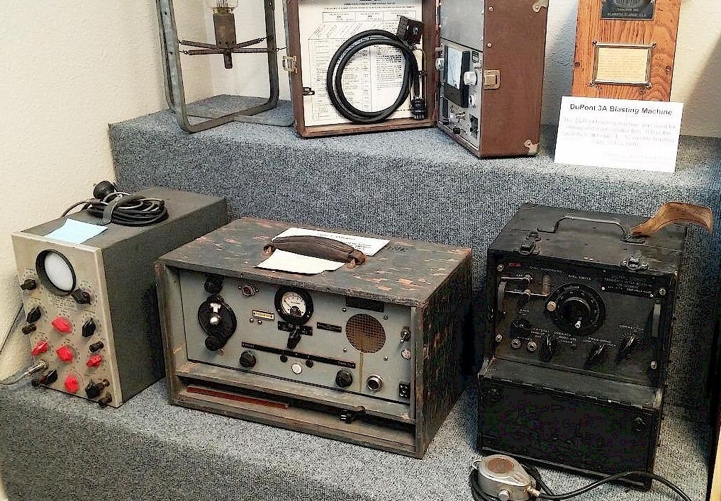
MUSEUMS
Here are a couple photos, courtesy of John Frye, of a US Forest Service display in a small museum in Salem, Oregon. If you have photos of forestry radios in museums. send them along and I can add them here! In the upper left shelf corner is the "Aluminum SPF # 1095."
TO E-MAIL ME: Geoff @wb6nvh.com
Ver. 11/8/20204 © Geoffrey C. Fors 2013 All rights reserved