
U.S. FOREST SERVICE
Type SX Portable Radio
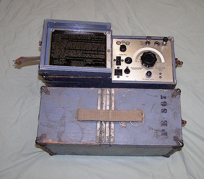
The Type SX is a 35 MHz VHF AM portable transmitter-receiver developed as an improvement on the Type S Radiotelephone and saw service in 1940 and for a number of years following WWII. The main improvement was that the Type SX contained a crystal-controlled transmitter while the Type S did not. It was designed by the Forest Service Radio Laboratory circa 1939 and at least the the Model A sets were made by Radio Specialty Co.. The example below, a Type B, was not.
During the war, other agencies adopted forestry radios, probably as an expedient to designing their own. The Signal Corps adopted the Type SPF Version AF high frequency portable radio for assorted uses, although it was never given a BC- type number, and interestingly, this example of the Type SX was produced for the U.S. Coast Guard and so labeled. This pair contains matching crystals in the 34 MHz operating range, and there are three transmit channels. The transmitter outputs about 250 Milliwatts, AM. The receiver is fully tunable across the design range. The transmit-receive function is handled by a curious plunger switch at the top of the panel. These sets arrived without any accessories, but originally would have used a microphone and a headset (as opposed to a telephone handset,) most likely a Trimm Featherweight headset and a small carbon microphone. The Trimm featherweight headsets were usually marked "US Department of Agriculture" on forestry radios, but as this model was a Coast Guard set, it probably had generic Trimm headphones.
The left compartment holds the necessary A and B batteries. A cable connects them to the battery power connector on the radio itself. Note that in this example, someone has switched the gender of the panel mount power connector. The cable from the batteries should have a female 4-pin Cinch Jones connector, while the panel mounted connector should be male.
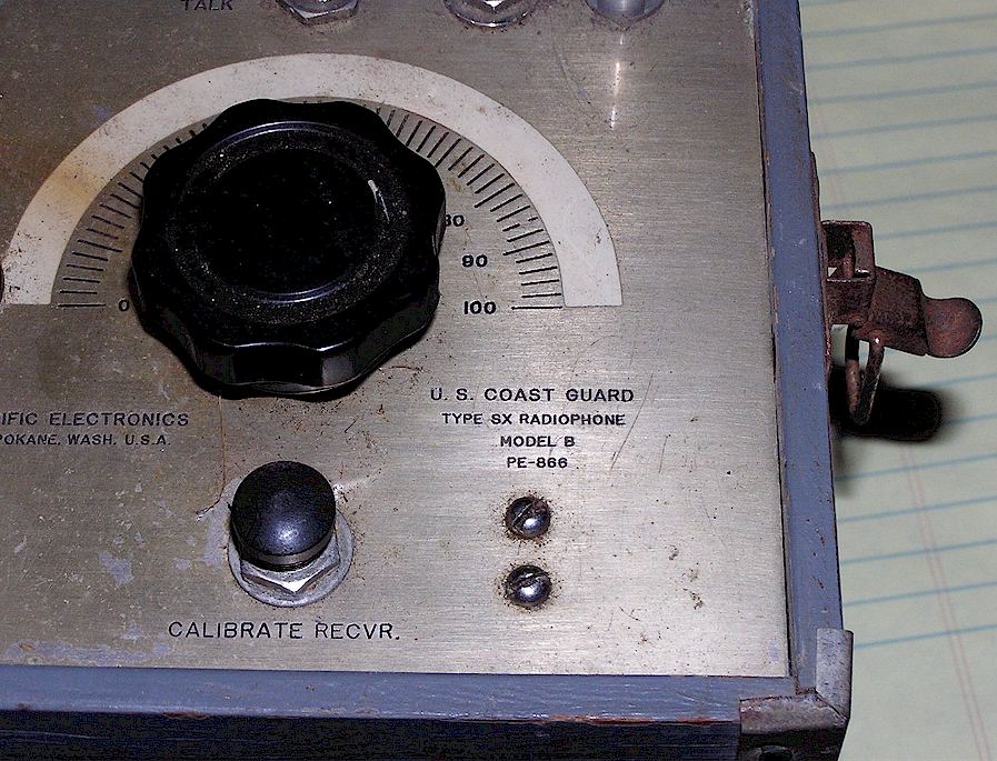
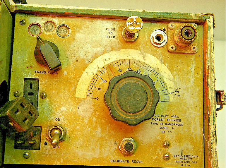
This example was manufactured by Pacific Electronics in Spokane, Washington for the Coast Guard. In operation, a quarter-wave length of insulated wire would be connected to the "ANT" binding post and thrown over the nearest tree branch. The small round socket was for an accessory called the "SXA," which today might be called a "docking station." This accessory was almost as large as the radio unit and provided an audio amplifier for standby use and from photos appears to have also contained a power supply.
Early models of the SX did not have this accessory connector. The "Calibrate Recvr" button would energize the transmitter oscillator section so that the operator could "spot" where his transmitting frequency was on the receiver dial. The comments on the website listed below suggest a 14 foot antenna, which would be 1/2 wavelength at 33 MHz more or less. This suggests that the impedance expected here is that of a 1/2 wave antenna. The socket next to the antenna binding post is presumably for a ground or ground counterpoise wire, i.e. the same 14 feet of wire thrown along the ground. Some sets in forestry service were modified to have a telescoping antenna, although it is not known where one would find such an antenna 14 feet long!
Additional data on the Type SX can be found HERE .
A somewhat usable schematic as well as a history of radio in the forest service can be found at K4OZY's page HERE , which is a readable scan of the hard to find book Radio For the Fire Line.
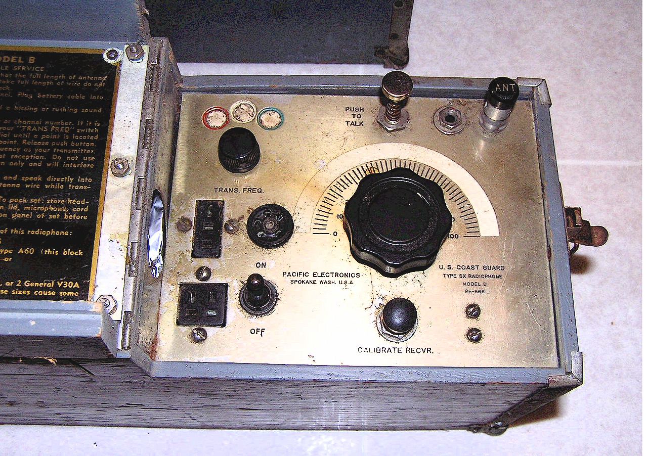
Note that the Cinch-Jones socket in the above photo is wrong. It should be a male chassis mount style.
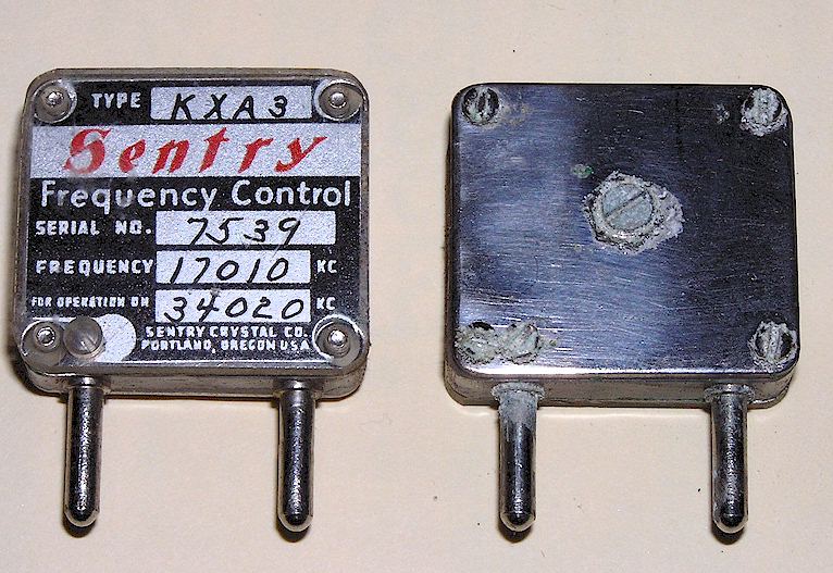
Typical crystals for the transmitter. Note that there is a tension adjusting screw on the back of the crystal case to "warp" the crystal on frequency:
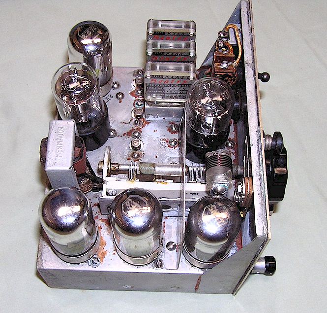
Interior view. a mixture of Octal and Loktal 1 Volt tubes.
US FOREST SERVICE VERSION
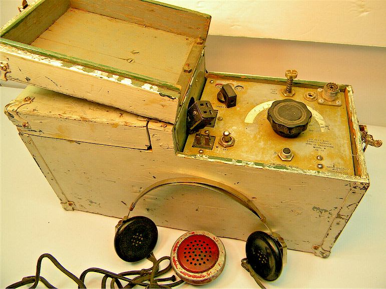
The example shown below is a US Forest Service version which showed up on eBay in November, 2019. As can be seen, it was in relatively atrocious condition, having been repainted numerous times and with an SO-239 connector where the original antenna binding post should have been. This one had the headphones and microphone, so the images are useful to show what those would have looked like.
Ver. 11--23-2018 Copyright Geoffrey C. Fors 2018 All rights reserved