CHP RADIO SYSTEMS
PART 3, Continued
1977-1988
THE ANTENNAS:
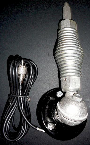
From approximately 1957 until 1997, the CHP used a black painted die-cast "ball and spring" style mobile antenna for the full size patrol cars, which was a full quarter-wavelength in size, mounted on the left rear upper quarter panel. Throughout the late 1950's and 1960's, this antenna often had a black painted spring as well. Sometime in the 1970's, the spring appeared in its natural stainless (or plated steel) color. Interviews with the radio service technicians who worked in that era indicate that directives from CHP headquarters were sent to the shops requesting that the antenna springs be painted black. The reason for this is unclear, other than perhaps to minimize sunlight reflections in the vision field of the officer or to make the antenna seem "stealthy." The supplier was the Antenna Specialists Corp. of Cleveland, Ohio. (Note - The CHP did not use the more expensive all-stainless steel Motorola ball mount on the regular patrol cars. That antenna can be recognized by a Saturn-like ring separating the ball's highly polished hemispheres, a gray plastic mounting base and an unpainted finish. There are some photos of such antennas in use on administrator and supervisor wagons and trucks, such as shown below, but they were not used on the standard patrol cars other than perhaps an isolated example or two.)
1950-60:
Shown below is a GE antenna supplied with the Pre-Progress radios above. Note the "General Electric" logo molded into the base disc. The ball is die cast. This antenna was used on the patrol cars from 1950 through the end of stock, probably in the early 1960's, when it was replaced by the Antenna Specialists "black ball" mount shown below it. This antenna also carries an Antenna Specialists ASP-633 part number, for the generic version not OEM'd to GE, and that type does not have the GE logo. The GE part number was 4033101-G1 and GE was supplying them off the shelf at least as far back as 1946. Note that the coaxial cable in the photo below is newer than the antenna assembly and not the original, which would have been RG-8/U cable. Note also that at least one other style of antenna was in use, presumably on cars containing the RCA radios, which was supplied by RCA. It looks almost identical to the GE part shown below except that ball is painted black without a ring at the parting line, and the spring has no hex flats on it. (photo to follow.)
Photo courtesy Alan Freeman
1960-1997:
Typical "black ball" Antenna Specialists mount in use through the 1970's-1997:
1974 Dodge Monaco, Photo courtesy CHP--> 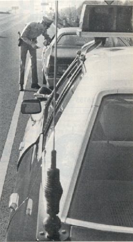
Some special applications also used the Motorola brand stainless steel ball mount, through the 1980's, as shown below:
1969 Dodge wagon, photo courtesy Dale Poppleton from late
summer '69 (footballs not CHP issue.)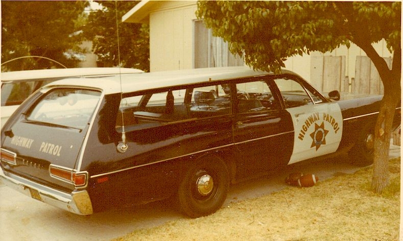
CLICK HERE TO SEE MORE PHOTOS OF THE CAR ABOVE
Beginning in approximately 1997, the CHP began installing rooftop antennas (Antenna Specialists) on the new patrol cars, and the ball and spring antennas were no longer used. The antennas for the GE VHF mobile repeaters first installed in the early 1980's were an 18" whip mounted on the rear center of the roof. Those antennas were a "wideband" model with a tapered spring and thicker than normal whip, by Antenna Specialists. When the main lowband antennas began to be mounted on the roof, that antenna was replaced by an "on glass" antenna cemented to the rear windshield glass. For a number of years after ABS brakes and engine management computers were first fitted in patrol cars, the original style ball and spring style antennas were often mounted on the passenger side quarter-panel of the vehicle instead of the normal method of left-rear quarter cowl-panel installation. This was evidently because of a problem with radio frequency interference to the automobile computer systems. Mounting of the antennas on this "wrong" side appears to have been on a case-by-case basis depending upon the particular year and model of vehicle and its computer system. When laptop computers began to be installed in nearly all patrol cars, the main two way radio antenna was changed to a roof mounted, loaded whip (due to interference to and from the computer.) By 1997 the roof mounted antenna should have been standard. Some of the Mustang patrol cars were already fitted with the rooftop antenna and an on-glass antenna for the "extender" by late 1992.
OTHER EQUIPMENT IN USE 1977-87:
DASH CONSOLES: Beginning in the mid- 1970's, the CHP installed the control heads on various styles of consoles or bracket trees mounted on the transmission hump of the vehicle floor, braced to the dashboard. In other words, the control heads were not necessarily bracketed to the dashboard lower lip as the manufacturers intended, but were instead attached to these frames. This is one reason why the control heads are never found on the surplus market with the brackets attached. The frames included some form of map lamp and space for a clipboard. In those vehicles, the frame would have mounted the radio control head, a Federal PA-20A electronic siren unit, and the radio speaker. The frames were made by the CHP shops, and were primarily of steel stock (and sometimes included painted plywood pieces.) Few have survived, and this is one of the most difficult aspects of the restoration of a vintage patrol car. If anyone has a good photo of one of these vintage consoles, prior to 1977, I would like a copy of it to place on this web page. Sometime later, after the adoption of the GE RANGR equipment, the sheet metal box-shaped console which mounted over the transmission hump became standard. It is also believed that various consoles and brackets were manufactured by Folsom Prison Industries.
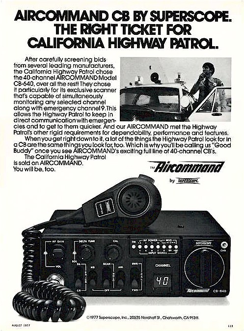
CB EQUIPMENT: There were a number of other radio devices installed in CHP patrol cars from the late 1960's through the mid 1980's. . During the CB radio craze of the late 1970's, CB radios were installed in practically all traffic enforcement cars, especially those in rural and interstate freeway areas. This took place in early 1977. These were usually identifiable by a black or fluorescent orange fiberglass CB antenna located on the rear deck lid center edge, or in some cases on a second standard CHP ball and spring base on the opposite side of the car from the CHP radio antenna. Some cars which came equipped with the CB radios from Motor Transport used a second CHP whip antenna for the CB.
There was some standardization of CB equipment throughout the state; the primary brand used was the "Superscope" unit although some equipment was purchased off the shelf from local department stores in some areas such as San Jose (Thanks to Nick Timashenka, retired, of the San Jose DGS Telecom office for this information.) The CHP divisions acquired the 1977 CB radios using non-recurring funds, primarily from a one-time federal grant, and the local Department of General Services radio technicians also purchased them "off the shelf" locally and retrofitted them at the CHP division garages and Department of General Services Telecom shops on those cars already in service. CB radios in patrol cars had generally disappeared by the late 1980's, although even today, commercial enforcement (trucks, scales, etc.) vehicles are equipped with them for the purpose of monitoring and communicating with truckers. The CHP official website, for some reason, seems to proclaim the installation of CB radios as a milestone event, when in actuality they were less than useful and the whole project was basically abandoned after the first purchase.
Note the interesting summer 1977 Superscope ad below. The officer and car in the photo appear to be "props" rather than actual CHP.
SCANNERS:
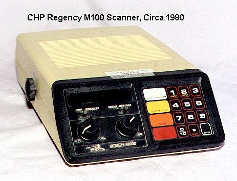
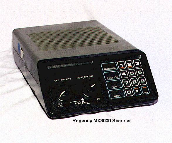
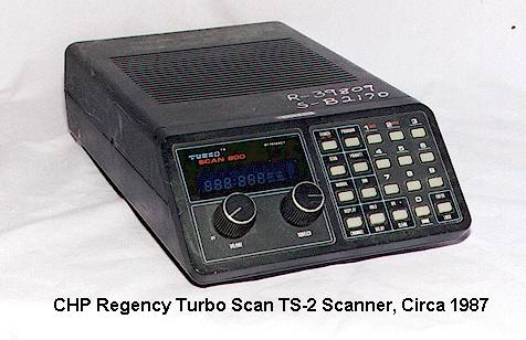
Scanners were installed in some of the CHP patrol car fleet in the 1973-80 period, and were initially Regency TMR- prefixed crystal control models, modified with a muting circuit such that when the patrol car radio went on the air, the scanner was disabled and muted. They were usually installed at the local level, in other words, there was not a fleet-wide large scale purchase of them. On June 30, 1980, the CHP ordered the new Regency programmable scanning receivers to be installed in all patrol cars on a fleet-wide basis.. These were Regency M-100 models, and were usually located under the dash to the right of the main radio control head and siren/lights control box. The M-100 scanners were also modified to have a "mute" circuit which would mute all sound from the scanner speaker during transmissions from the patrol car's Micor CHP radio (to prevent background noise and feedback interference). In 1983, Regency also sold a quantity of model MX3000 scanners to the State of California, primarily for the Transportation Agency (CalTrans), and those were also used by the CHP in 1983-87 together with the older M100 scanners. All of these scanners were used into the late 1980's and replaced at new car builds at the end of 1987 with the Regency TurboScan 800 (TS-2) scanner, which seems to have remained in service through the early 1990's. The TurboScan 800 scanners were in turn being replaced, starting in approximately late 1989, with Uniden MR8100 public safety scanners, which feature computer programmability and an alpha-numeric display. One possible reason for the somewhat short life of the TS-2 was that Regency had gone out of business in the meantime, although Uniden picked up the factory support for the scanner line as far as what spare parts were left.
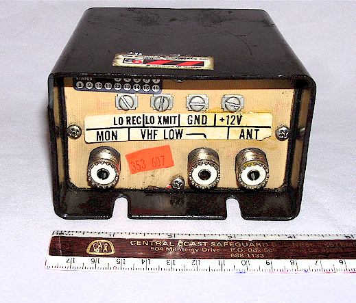
The MR8100 probably represents one of the most interesting scanners ever made, despite its use of somewhat cut-rate components. By 1996 the Uniden scanners were in turn being replaced by the Bearcat BC760 scanner, sometimes mounted in-dash in some vehicles, a departure from the "everything in a console" style of years past, but usually mounted in the lower rear of the standard sheet metal console box. See later pages for photos of the BC760 in use. Some Uniden MR8100's are still in use as of 2008, surely a record for scanner longevity in the CHP, although most were replaced after about 2000 with the Bearcat units (see later history pages.) The scanners use a "coupler" box which allows them to share the low band antenna or the "extender" antenna on the vehicle and be disconnected from the antenna when the mobile transmitter goes on the air. The initial examples of these "coupler" or "relay" boxes were made at CHP and DGS Telecom shops, although by the early 1990's these boxes were being manufactured by Antenna Specialists as custom order items.
PLEASE NOTE: I have a separate web page which details modifications to the Regency M-100 to allow extended band coverage, including the 10 and 6 meter amateur ranges. Click here to be redirected: M100
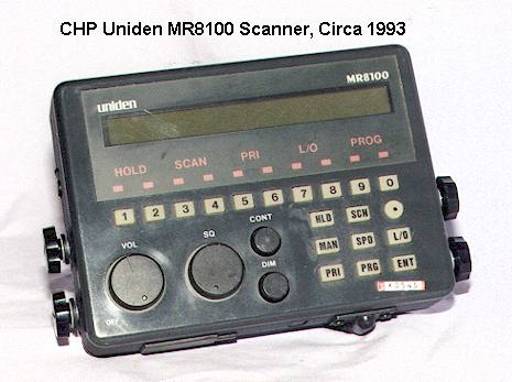
Notes regarding the Uniden MR 8100:
The original design of the MR8100 called for a rocker switch for the on/off function located on the right side, along with a BNC antenna connector below it. However, this prevents the unit from being placed inside a vehicle console. The CHP version uses an on/off switch integral with the volume control and a short pigtail with a BNC connector for the antenna. Uniden referred to this model internally as the MR8100A, although the scanners themselves as the paperwork and shipping cartons were still marked as simply MR8100. There seems to be no way to tell the difference without inspecting the unit. The rocker switch MR8100 is uncommon and it is believed that the vast majority of 8100's have the power switch on the volume control. Note that former CHP MR8100's will have the small foil inventory number sticker on the front panel somewhere and an "R" and "S" number painted crudely across the top edge, as seen on the Turboscan model shown above it.
A fair number of these scanners are starting to fail now that they are over 20 years old. On all of the examples I have overhauled, the issue has been shorted electrolytic capacitors, which cause the fuse to blow or otherwise disable the equipment. This seems to be a characteristic of all Uniden equipment of the early 1990's - - the use of electrolytic capacitors with voltage ratings too close to the voltage of the rail they are connected across. The solution is of course to replace these defective capacitors, however you should use ones rated at least 10 Volts more than what you take out. Using a 16 Volt rating capacitor on a rail which regularly runs 14 Volts is not good engineering practice. In situations where the capacitor/s have not already blown the fuse, you can often find them by feeling them, as they will range from hot to very hot. They can also be found with any VOM as they will measure close to a dead short. This issue was occurring at CHP by the late 1990's.
I have noticed that there are a couple of people on eBay selling copies of the simple instruction manual and the software for these. Please note that these are available as free downloads from various sources and there is no reason to pay for them.
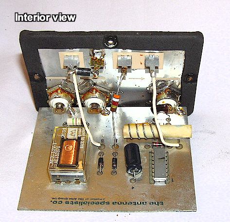
ANTENNA RELAY - COUPLER BOXES: In approximately 1980 it was determined that a relay-coupler box which would use the existing two-way radio antenna to also feed the scanner was desirable. Initially designed by state and CHP engineers, the box was in production by Antenna Specialists by 1981. It basically disconnects the scanner from the main radio antenna when the main radio antenna is being transmitted on. I have no part number on this box and it appears that Antenna Specialists made these exclusively for CHP and never sold them as a catalog item. The housing resembles a mast-top TV antenna preamplifier box and is made of hi-impact plastic. The face of the box is a fiber material sometimes used for inexpensive circuit boards.
RADAR: The CHP traditionally did not use radar, mainly because it had no budget for it, into the 1980's. However, in some high-accident-rate areas radar was used, which was usually paid for and provided by local organizations including cities, counties, and civic groups. The radar equipment in the 1980's was typically older model Kustom Signals X and K-Band equipment; there was no standardization. Into the early 1990's, older Kustom KR-10 (and KR-11?) equipment was still seen in use although newer Kustom Signals Hawk equipment was also being bought.
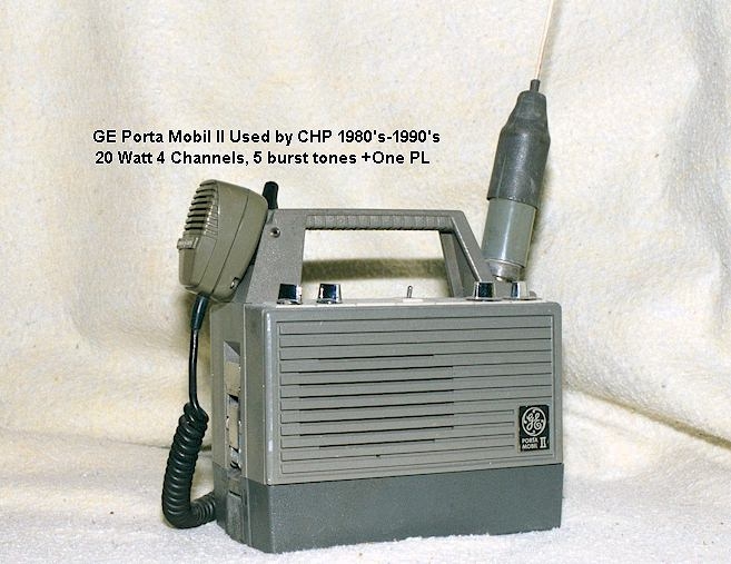
SPECIALS: There were many special radios produced by Motorola, RCA, GE and also the CHP's own radio personnel. These included 1970's-80's era portable base stations and repeaters built into aluminum Zero-Halliburton carrying cases, and GE Porta-Mobil II low band 20 Watt "lunchbox" pack set radios (used for special events and command posts). Motorola L01F tube type desktop monitor receivers (circa 1954) were extensively used in stations and were later replaced with Motorola M01CNB series solid state sets (1968). In some instances additional mobile radios on other-agency channels were installed in special purpose vehicles, upon request, although these were rare. Generally, other agencies did not want to allow CHP vehicles to be able to transmit on their channels, especially since the CHP was technically not licensed to do so. This is an inter-operability problem which continues today on a nationwide basis!
SIRENS/EMERGENCY LIGHTING CONTROL BOXES:
Until approximately 1977, the CHP controlled the emergency lighting via a row of toggle switches mounted on a metal plate installed where the broadcast radio would normally be. The plate included a pilot lamp. The switches in that plate, from 1960-77, were 1) "Radio inside-outside," 2) "Siren-Horn" for the mechanical siren to horn-ring connection, and 3) the on/off switch for the rear yellow/red rear deck lamps (center "Off.") This plate, at least in the Dodge vehicles, also had some warning language about turning off the air conditioner above a certain high speed!
After 1977, the CHP began using an integrated lighting control and siren unit made by Federal Signal, the model PA-1000-8Z. The full model number of the PA-1000 was PA-1000*012-8Z and it was a special production version made specifically for the CHP. The special features mainly involved the function selector, which deleted the "Hi-Lo" sound and "Yelp" functions from the function switch, although there was a timer circuit which activated the "Yelp" feature via the horn ring contact, and then reverted to "Wail" after a predetermined time. The photo below shows the interior of a 1978 Monaco. The siren front panel functions were "Manual," "Radio," and "Wail." The "Radio" feature connected the radio speaker line to the outside PA speaker via the siren amplifier. Statements from retired officers indicate that some of these PA1000's were also either the standard model or a variation of the 8Z which did in fact include the YELP and RIOT modes.
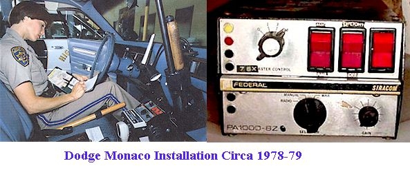
Notice that in the above photo, interestingly, there is neither a CB nor a scanner in evidence...
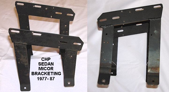
From the 1977 Micor installations onward, CHP began to use a standardized mobile mounting "console" consisting of a hand welded steel rack affair which mounted over the transmission hump on the vehicle floor. Below is a clearer view of one of these racks. The later CC-1* siren and lighting control also fits in this rack, although it is not known whether the CHP modified the racks to take into account the lower total height of the Micor control head and the CC-1* console compared to the earlier PA-1000 setup. Note that the rack in the above photo appears somewhat different and has the microphone hung across its front rather than the side. There were obviously several rack styles in use, and variations over the years.
The Federal CC1* Equipment
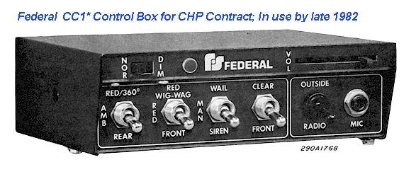
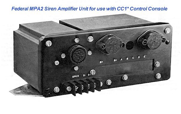
In June 1982, the CHP entered into a contract with Federal Signal of Chicago to produce a custom siren/lighting control console for the patrol cars. This model was the CC1*, which controlled the MPA2 siren amplifier (100 Watt). Shortly after installation, many of the CC1* consoles were modified to include an extra switch and a blue pilot light on the upper edge, which was used only in cars equipped with the Federal Jetsonic light bars, to cut-off the front lights on the light bar. The blue pilot lamp was to warn the officer that the front-facing lamps were in the "disabled" mode. This modification was not made on the CC1* used in cars with "slick-tops" (no light bar) and Mustangs. (Thanks to Mike at SpecialServiceMustang.net for figuring out this info).
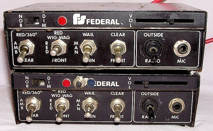
Like the PA-1000 8Z before it, the CC1* did not feature the "Yelp" mode as a front panel switch option, although it was technically available via the horn ring switch (Federal called this the "Tap II" mode) depending upon the wiring arrangement chosen. It is believed the CC1* was only supplied to CHP as no other agency has been found which used them. The photo immediately below is a scan from the service manual and the one below it of two actual units removed from service. It almost looks as if the "VOL" slide control is missing a knob, which could have been fitted, but that's the way they were delivered. This makes it inconvenient to adjust the PA volume, but perhaps it was rarely necessary to do so.
Shown below are the two versions of Federal CC1* used by CHP, the bottom example having the added front lamp cutout switch and blue indicator lamp for use on light bar equipped cars. The "NOR-DIM" switch refers to the panel illumination; there is a lamp with a blue lens which shines onto the switches via a cutout slit on the upper panel approximately where the "Federal" logo is. The upper example would be found in "Slicktop" and Mustang cars while the lower, in cars with a rooftop light bar.
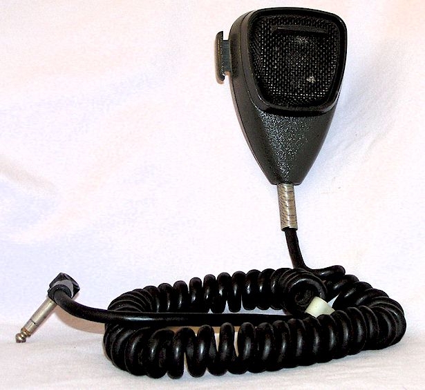
Shown below is the noise-canceling microphone supplied by Federal for these units, which I believe is an Astatic item OEM'd to Federal. Note that during the production period, both gray with black grille (shown) and all black versions were supplied. The connector is a molded-on standard 1/4 stereo style plug. There was usually a white plastic strain relief clamp around the cord which clamped the cord to the right front screw under the CC-1* console, preventing the possibility of the cord being pulled out inadvertently.
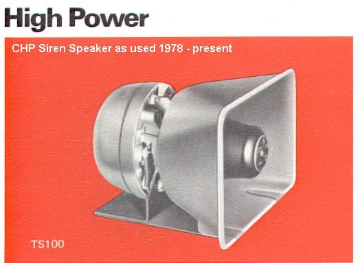
The TS-100 speakers as used were all-black in color.
Starting in early 1988, and continuing for a number of years, the CC1* equipment was retired as cars were taken out of service, and replaced with the GE RANGR integrated radio/siren system, where the siren, lights, shotgun lock and so forth were controlled from the radio control head, which in turn controls a relay box in the trunk via a serial data line. Light bars, when used, were wired to a Federal Signal control-junction and relay box in the trunk. Shotguns in the passenger compartment were discontinued with the introduction of the laptop mobile computers, although in recent years they, along with CAR-15/M-16 rifles, have returned, mounted vertically between the left and right front seat backs due to passenger-side air bag requirements.
Here's an example of the radio card kept in some cars. Courtesy Don Schafer.
Ver. 6/16/2020 © Geoffrey C. Fors 1998 All rights reserved