CHAPTER 1
THE FIRST CAR TELEPHONES, 1946-53
INTRODUCTION
The first car telephones connected to the Public Switched Telephone Network in the United States were put into service in 1946, as a response to the growing mobility of the American population in the postwar years. Initial design of the mobile telephone itself was undertaken by the Western Electric Corporation, the prime supplier of telephone sets to the nation's Bell System operating companies, while Bell Laboratories itself designed the overall system and set the specifications for the equipment. At the same time, the independent telephone companies were developing their own equipment, to be supplied by Automatic Electric. The Bell System equipment built upon an already existing mobile radio set, Western Electric's 1945 vintage Type 38 or 39 VHF FM police radio equipment, adding a telephone style handset and a selective calling decoder, which rang a bell in the automobile when that phone's unique number was signaled. The selective calling decoder consisted of a small wheel in a glass enclosure, with pins located at certain points around its circumference. The decoder had been developed in the 19th century for railway right-of-way signaling, was later used in ship to shore radio telephone installations in the 1930's, and was a proven concept. This decoder was labeled "102." Western Electric and the Bell companies thus did not draw up an entirely new concept for a car telephone in 1946; they used proven components of other systems to create the new public car telephone service.
Mobile telephone equipment had already been in use internally within the Bell System on an experimental basis, going back before WWII, using mobile radios such as the Western Electric Type 28 VHF equipment. One example was the Emergency Radiotelephone Service established by New York Telephone in December, 1940, which used AM on the 30-40 Megacycle band. Based on the successful tests of that equipment, AT&T announced the creation of the General Mobile Radiotelephone Service on June 29, 1945, and applied to the FCC for authority to establish base stations in Baltimore, Chicago, Cincinnati, Milwaukee, Philadelphia, Pittsburgh, St. Louis, Washington DC, Columbus Ohio, Denver, Houston, New York City, and Salt Lake City. One has to wonder why nothing was initially considered for California.
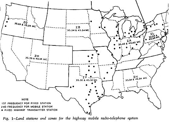
The FCC and the Bell companies envisioned two forms of mobile telephone service, "HIGHWAY" and "URBAN." Both would be VHF, and both would use FM. The "Highway" service, as its name implies, was intended primarily to serve the major land and water routes that existed across the United States in the 1940's, which would not be served by the "Urban" systems. Highway service was intended for trucks and barges on inland waterways rather than private vehicles. Highway service was allocated 12 channels in the VHF "low band," with the mobile equipment receiving on 35 Megacycle and transmitting on 43 Megacycle frequencies, although not all 12 channels were initially used. The Urban equipment, as its name implies, was intended to serve mobile subscribers whose travels took them primarily within the immediate radius of a major urban center, such as doctors, delivery trucks, ambulances, newspaper reporters and so forth. Urban equipment operated on VHF 152 Megacycles (receive) and 158 Megacycles (transmit,) and the initial FCC allocation in 1946 was for 6 channels. The separation in transmit and receive channels was necessary to provide a "half duplex" communications circuit, and allowed the telephone company base station to remain on the air continuously during the duration of the call. The first Highway system went on the air in August 28, 1946 in Green Bay, Wisconsin, and the first Urban system went on the air in Saint Louis on June 17, 1946.
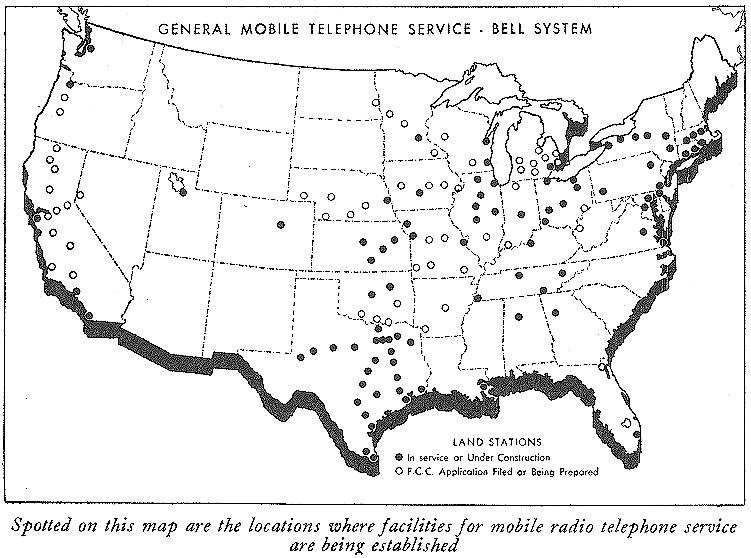
By 1948, Urban service was available in 60 cities in the United States and Canada, with 4000 mobile subscribers, handling 117,000 calls per month. Highway service was in place in 85 cities with 1900 mobile subscribers, handling approximately 36,000 calls per month, with most major highways in the east and Midwest covered.
The Bell System also entered the two-way business and police radio market after the war by offering the rental of entire radio systems including their maintenance and updating. This equipment was marked "Bell System" either in white painted letters or with water-slide decals. Smaller police departments were encouraged to use the "Urban" mobile telephone system as opposed to a traditional dispatch system, which must have been somewhat odd in operation. Most of the equipment rented by the Bell System affiliates was Motorola two-piece "Deluxe" equipment, FMTRU-5V "Dispatcher" and GE one-piece pre-Progress Line radios. It is believed that the Bell System discontinued this practice sometime in the early to mid 1950's.
Map of Mobile Telephone Land Stations in Service or Planned in early 1947:
Map of first "Highway" Mobile Telephone Land Station channel assignments, early 1947:
ORIGINAL URBAN SIX CHANNEL ALPHA-DESIGNATORS:
WJ WR JL JP JR JS
ORIGINAL HIGHWAY ALPHA CHANNEL DESIGNATORS:
ZF ZH ZM ZO ZB ZA ZL
POST-NARROW BANDING ALPHA CHANNEL DESIGNATORS:
(After 1964)
Highway: ZO ZF ZH ZM ZA ZY ZR ZB ZW ZL
Urban: JL YL JP YP YJ YK JS YS YR JK JR
UHF: QJ QA QP QB QR QF QS QH QW QL QX QM
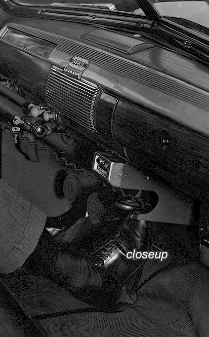
Typical installation of the first car telephone:
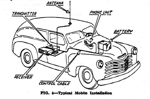
WESTERN ELECTRIC 238 and 239 EQUIPMENT AND 41A CONTROL HEAD
The Western Electric house-made equipment consisted of two pieces; the transmitter cabinet and the receiver cabinet. These mounted in the automobile trunk, and a large cable brought forward under the carpet connected to a "control head" under the dash which contained a telephone handset. The control head featured two illuminated lenses--one indicated that the equipment was turned on, and the other would illuminate when the mobile telephone was called. The Western Electric Type 38 was Highway band equipment, i.e. VHF low band, and the Type 39 equipment was Urban, or VHF high band equipment. A complete installation would be prefixed "2"; in other words, type 238 would be a complete Highway mobile telephone, and type 239 a complete Urban mobile telephone. As originally supplied, all equipment was single channel in operation although two channel expansion was possible.
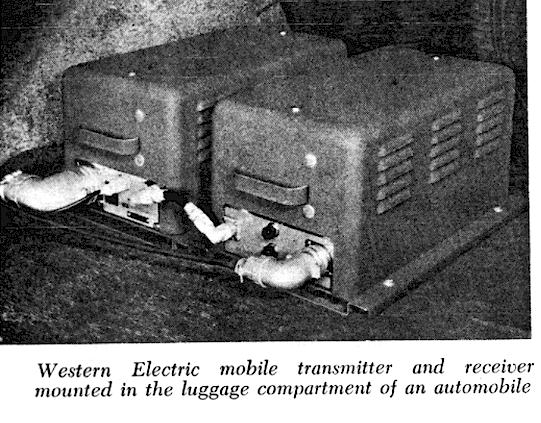
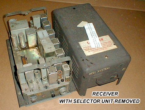
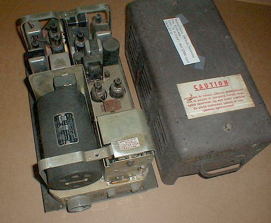
Transmitter shown below
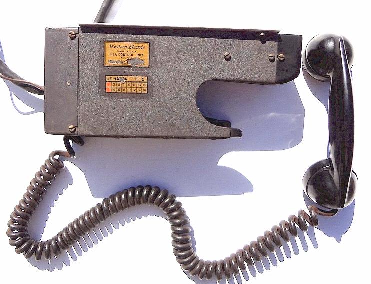
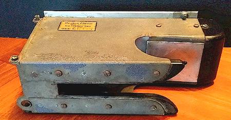
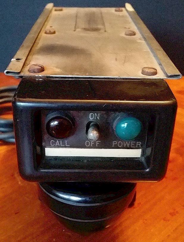
The first Bell System mobile telephone control head was the Western Electric Type 41A, seen below. The handset, with a cloth braided cord, stores in a curious-looking spring loaded pocket on the bottom of the control head. The bell and terminal strips for cabling are self contained in the 41A. There were two styles of 41A control head; the difference was only in the faceplate around the pilot lamps and toggle switch. The original 41A had two exposed lamp lenses as shown. The later model had a smooth plastic sheet with colored lens sheet pieces set behind it. The 41A set was technically a single-channel installation although a multi-channel switch was developed which mounted alongside in a separate box.
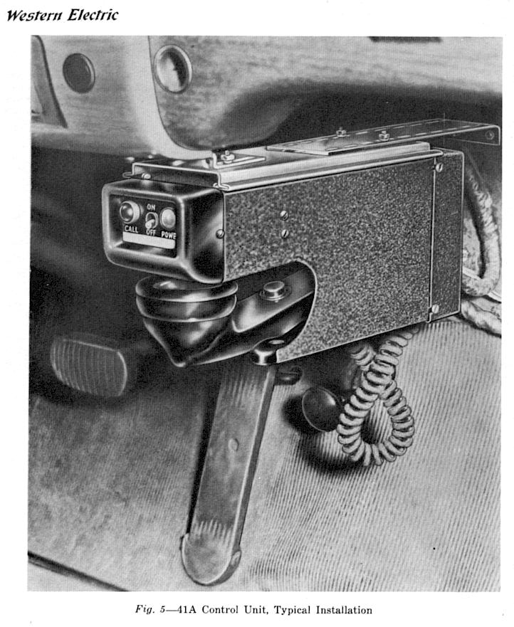
Type 41A Control Head with non-original rubber coiled cord, a later replacement:
The equipment for decoding a ringing signal to a particular car was a rotary stepper wheel with a latch, designed to count inbound pulses as they were dialed from the land side station, located on a chassis called the "Selector.". The land station's signal consisted of alternating pulses of 600 and 1500 Hz tones representing the various numbers. The description of how this worked is below. If all the right numbers were received, the wheel would reach the end of its travel and a bell would be activated either inside the control head (41 Series) or (later) in a bell box under the car dash (47 Series.)
In 1949 a typical number scheme for the equipment was as follows:
Transmitters
Type 38B
Urban 6 Volt
Type 38C
Urban 12 Volt
Type 39A
Highway 6 Volt
Type 39B
Highway 12 Volt
WETU-30-D
Urban Motorola Deluxe 6 Volt
WETU-30-12D Urban
Motorola Deluxe 12 Volt
In the type 38 and 39 receivers, the decoder circuitry was mounted inside the receiver chassis. Western Electric also manufactured a separate housing for this decoder, such that it could be used with other makes of mobile radio equipment, such as the Motorola "Deluxe" line two way FM radios and the GE 1949 "Pre Progress Line" two piece sets. The separate Selector Set was called the 106A. See below.
CLICK HERE FOR A PHOTO OF A LATE TYPE 41A HEAD IN USE
WESTERN ELECTRIC 106A SERIES SELECTOR SET:
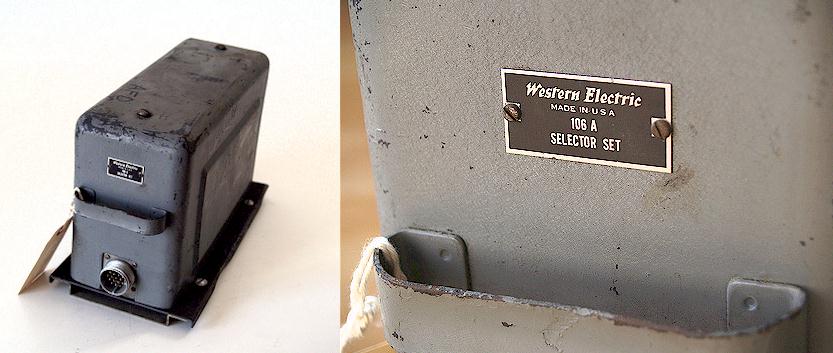
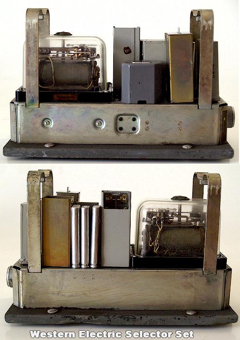
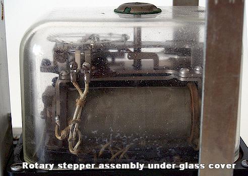
The decoders in these sets were capable of responding to a maximum of five digits, and operated by a series of small pins placed in holes around the circumference of a toothed ratchet wheel. As the operator dialed a specific mobile unit, all the wheels in all of the mobile phones within range would begin to move in step with the pulses being dialed from the telephone company's base station. At the end of the first digit, only those mobiles with pins in the wheels set to that number would hold the wheels at that spot. The others would reset to the rest position. This process would continue through the fifth digit, at which point (ideally) all the decoder wheels in the other mobile phones would have returned to the rest position except the one whose five pins matched the number dialed by the operator, at which point the wheel would close a switch and the mobile's bell would ring. The signals from the telephone company were audio tones, alternating between 600 and 1500 cycles as a digit was dialed. It was possible to hear the stepper wheel operating in your trunk with calls for other people, and even to anticipate when your phone would ring by listening to the stepper ratcheting.
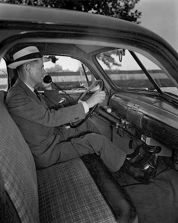
This first system of mobile telephony would come to be referred to as "MTS." There were no dial facilities in the cars - - to initiate a call, the push-to-talk button would be depressed briefly, which would cause a lamp to light at the mobile operator's switchboard and put the base station at the telephone company on the air. The mobile unit would give the operator its telephone number and city of registry, and the desired number to be dialed. The mobiles were not "duplex," i.e. operation of the handset pushbutton was "push to talk," and "release to listen." The majority of the mobile telephones had no squelch circuit, so the characteristic FM "rushing" noise would emanate from the handset whenever the base station went off the air. This was not a problem since the handset audio was muted whenever it was hung up on its cradle.
Equipment manufactured by Motorola (the "Deluxe Line") was also placed in service together with the Western Electric, principally on the "Highway" channels, along with a small number of GE two-piece FM transmitter-receivers (also for "Highway" service.)
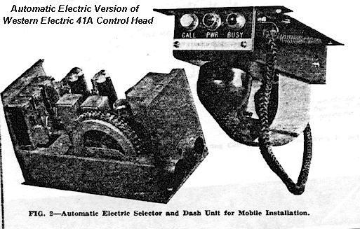
Independent telephone companies utilized equipment nearly identical to that of the first Western Electric car telephones, which was manufactured by Automatic Electric Co. as shown below, and believed to have been used with Motorola and GE radios:
MOTOROLA "DELUXE" LINE ADAPTED FOR MTS USE:
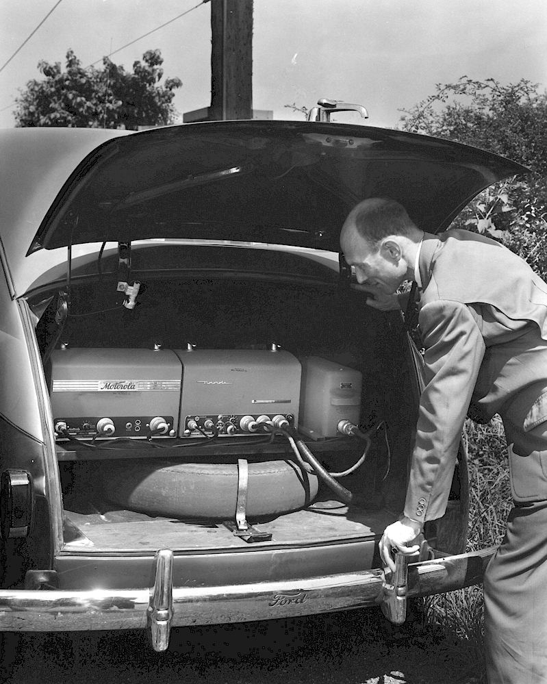
The photo below shows a Bell System Motorola "Deluxe" line high band ( 150 MHz) "Urban" radiotelephone installed in a taxicab in Delaware in 1948, taking up practically the entire trunk. Many of these units had a sheet metal plate tack welded to the upper cabinet lid covering the connector area. This was to keep the connectors and cables from being bashed to pieces by things being thrown into the trunk, and were usually seen in taxicabs.
The Type 106A rotary signaling selector unit is shown on the far right. The receiver would have been a model FMRU-16V modified for Western Electric use and (apparently) renumbered WERU-16-V (for a 6 Volt receiver.) The transmitter would have been the WETU-30-D ( 6 Volt Urban dynamotor powered transmitter) which in Motorola numbering was the FMTU-30D.
The cabinets on these units show that they have been "recycled" by the Bell System already -- one is slightly older than the other and they don't strictly match. These were regular two way radios modified for Bell System use by incorporating the external selector unit and a telephone-like control head.
In the picture below, the far left is the receiver, the center the transmitter, and the far right the 106A Selector Set.
Notice that this guy should be shopping for a new spare tire!
Land Station Side
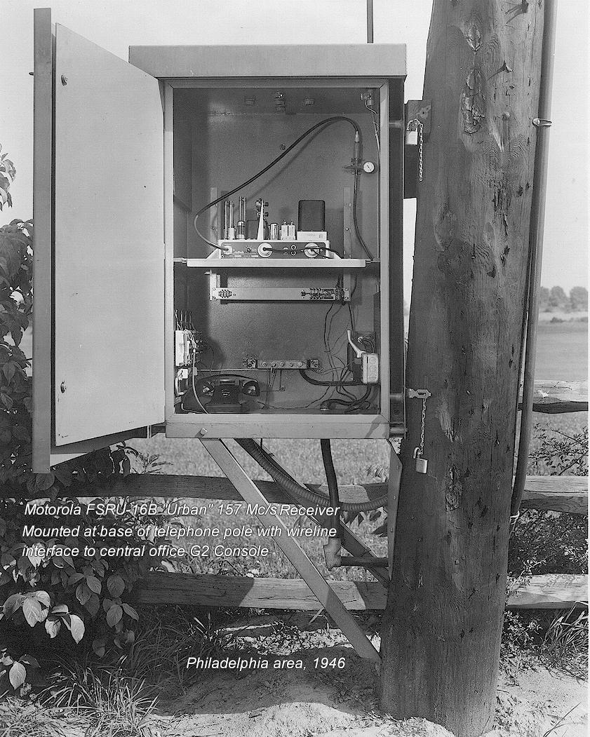
Below is a photo of the typical remote receiver used to feed the signal from the mobile phones to the central office operator board, in this case called the G2 Console. They were mounted in a weatherproof cabinet at the bottom of a telephone pole, with the antenna at the top of the pole fed with gas filled concentric cable. There were usually several of these receivers located at strategic points, but only one transmitter. This one was outside Philadelphia and uses a Motorola FSRU-16B receiver on 157 MHz..
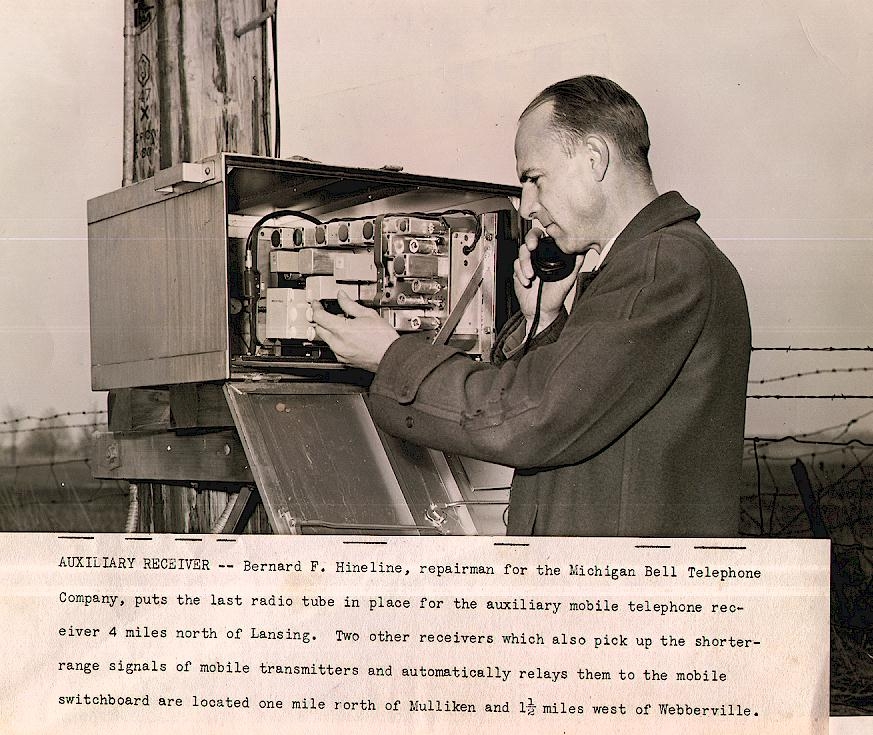
REMOTE RECEIVER USING WESTERN ELECTRIC TYPE 38 EQUIPMENT:
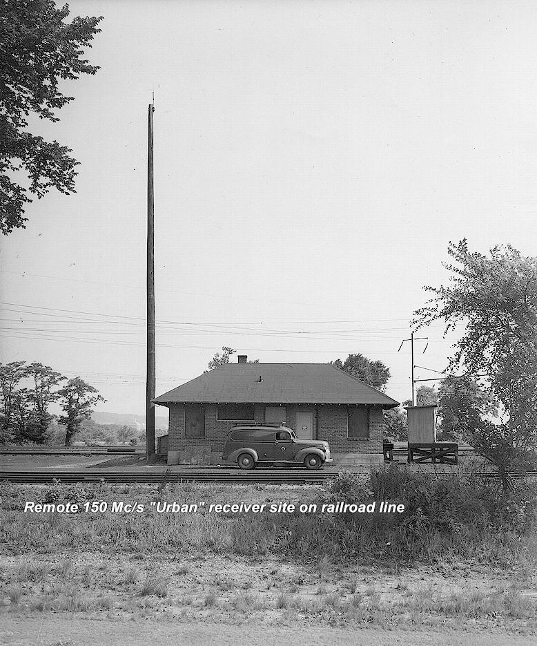
The view below shows a remote receiver site where the receiver itself was inside a railroad right-of-way building which seems to have once been a small station, already boarded up by 1947, somewhere near Philadelphia.
Shown below are typical views of a central office switchboard and equipment. In this case, Philadelphia, 1946, the Western Electric G2 control console. The racks represent the console in the switch area of the telephone plant and the wooden switchboard and toll-ticket printer are inside at the main operator area. Note the Western Electric "Urban" and "Highway" VHF receivers mounted along the tops of the rack frames. The transmitter was located elsewhere.
The caption for the photo below reads:
"Western Electric G2 Control Terminal. Terminal facilities for mobile telephone service in the Philadelphia area include four Western Electric G2 Control Terminals. The cabinet type at the left is for the Philadelphia link in the New York -- Washington Highway System. The first rack mounted type at the left is for the Philadelphia Urban channel # 1 (FCC # 11.) The three square boxes over the fuse panels are filters in the incoming AC power lines to reduce noise. The receiver at the top is for monitoring. Each of the receivers at the top of the racks are for monitoring their respective channels. The middle rack Type G2 is for the Philadelphia Urban channel # 2 (FCC #9.) The right hand rack Type G2 is for the Urban channel # 3 (FCC # 7.) Railroad service for the New York to Washington run is also also handled on this channel. The apparatus just over the G2 equipment on the right hand rack is an A1 noise reducer J6806L1 and an appliqué unit used in connection with the railroad service.
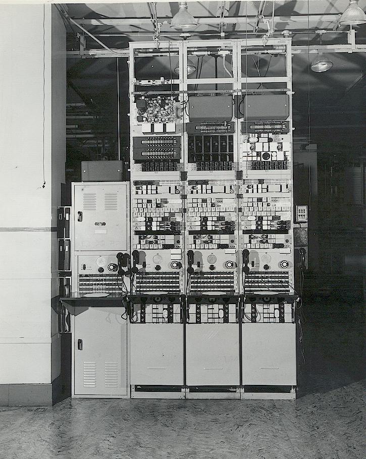
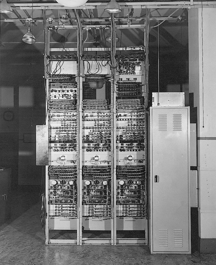
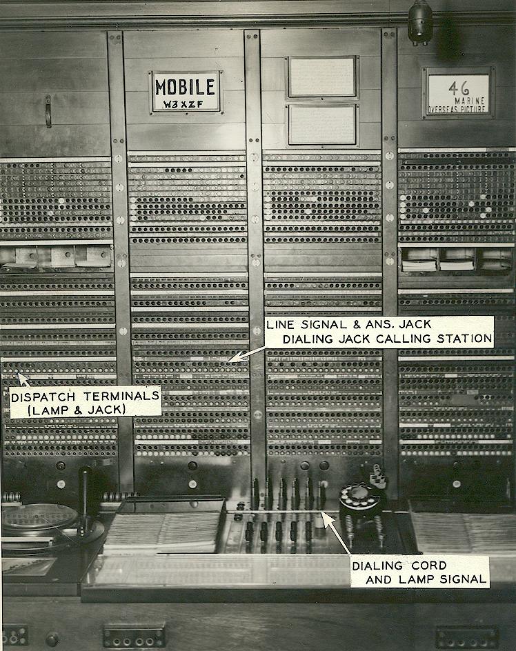
Photo below of mobile operator in Michigan Bell central office. Back of photo reads: "MOBILE SWITCHBOARD - - Calls to and from mobile units are handled by a special 'mobile service operator' in the Michigan Bell Telephone Company's main office. Miss Pat A. Voige is shown as she completes the first calls over the new system here. "(1948)
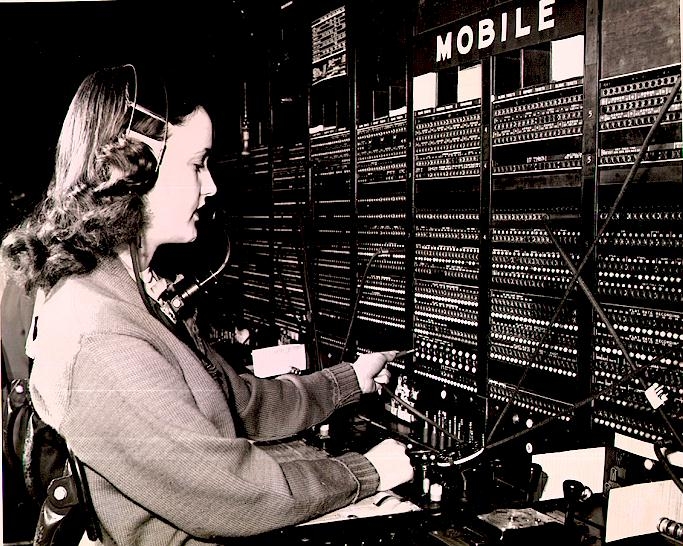
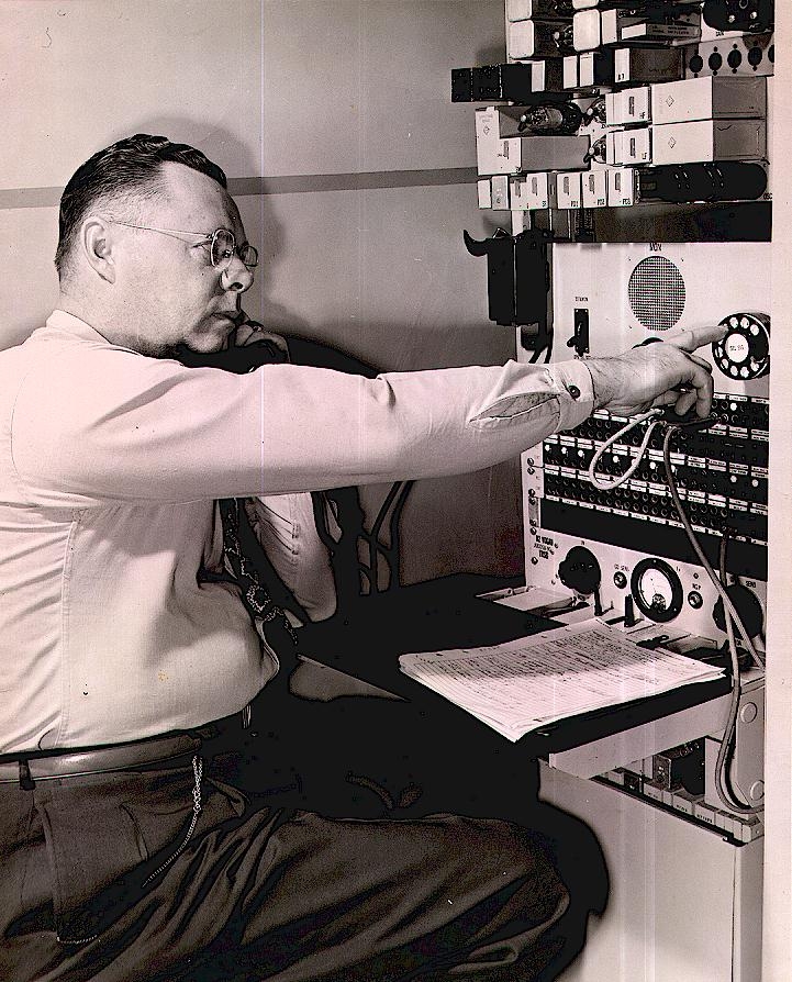
Photo below reads on back: "Leslie F. Hamelin, toll technician, keeps a close watch on strength and quality of signal at control center in central office building. (Michigan Bell, March 1948)
MOBILE PHONES ON TRAINS
CLICK HERE for the page showing a 1947 mobile telephone system installed as a public phone booth on a Pennsylvania Railroad train.
BELL SYSTEM SHORT FILM
CLICK HERE for a short film from approximately 1948 showing the first Bell System phone systems in use.
EARLY CAR TELEPHONES ON TV
There are assorted films and TV shows which made use of the earliest mobile telephones. I hope to list them here as they become known. In many cases only the handset is shown and it can be assumed that there was no actual control head and only the "prop" handset was used. But some show the entire control head. Some movies, while attempting to feature car telephones, show only complete props or other fakes. An example would be Sabrina, starring Humphrey Bogart, which unfortunately shows only a fake mobile telephone control head and a ridiculous gigantic antenna on the limousine it's mounted in. Genuine early MTS car telephone sightings are listed below:
1) The Feb. 15, 1960 ( Ep. 21 Season 2) episode of Peter Gunn, TV detective show, entitled "The Hunt," features the Type 41A control head in Gunn's car, at approximate time hack 10:08 . Great view of the control head.
Unfortunately these episodes are endlessly being removed by YouTube following copyright infringement claims and there is no way to make a link work here for longer than a few days!
2) A few other Peter Gunn episodes circa 1959-60 show him using the same MTS mobile telephone as well, such as the January 4, 1960 episode (Ep. 15 Season 2) entitled "Hot Money" (you can skip ahead to approximately 20:40 if desired.)
04/24/2021 © Geoffrey C. Fors All rights reserved