CHAPTER 5
The Growth Years, 1964-70
Introduction of IMTS
On November 1, 1963, as part of the nationwide "narrow banding" of the two way radio spectrum, the FCC split the six MTS VHF mobile telephone channels into eleven, creating enough room (at the time) for more subscribers and newer design equipment.
Bell Laboratories had been slowly mulling the expansion and growth of the mobile telephone industry for many years, and some developments felt important in that regard were the need for automatic dialing from automobile subscribers, direct dialing to those mobiles from land based phones, and most importantly, channel trunking. Channel trunking refers to the ability of a mobile unit to search for an idle channel in order to initiate a call; this allows far greater loading of customers on a particular system than the old arrangement of a fixed number of subscribers "camping" on their particular "home" channel.
The rarely-mentioned reality is the decision to implement "direct dial" mobile telephones, or not, was primarily a political one within the Bell System administration rather than a technical issue. The details are beyond the scope of these pages, but AT&T was in no hurry to implement direct dial in the mobile service. The technology had already been there for some years to perform automatic call completion, it was only the automatic channel hunting of IMTS that had to wait for the transistor to become available. Thus it would be wrong to say that the Bell System and AT&T's mobile service was driven by technology...it was driven by accounting ledgers, politics, state tariffs and FCC cooperation (or lack thereof.) California, by way of major example, failed to switch to IMTS until 1982!
The solution for the "New" mobile telephone system was "IMTS", short for Improved Mobile Telephone Service. Initially the name had used the "I" for "interim," but future improvements were not so near in the future and it was the word "Improved" that stuck.
The development of the IMTS system was undertaken by the ITT-Kellogg Corporation, Secode Corporation, and Motorola, all of which received development contracts from Bell Laboratories. ITT for the control equipment, Motorola the radio gear, and Secode the control head. This was particularly vexing to Secode, which had developed IMTS some time earlier and thought they would be awarded the control terminal contract as well.
A "test" IMTS system consisting of three channels was set up in Harrisburg, Pennsylvania in 1963, and used by mobiles registered to Bell System company vehicles of the Bell Telephone Company of Pennsylvania. This test system was demonstrated to telephone company executives from across the country, and also to representatives of the FCC, with the first installation of an actual public IMTS system inaugurated in Charleston, West Virginia by November, 1964. The mobile equipment used was the Motorola TLD1000 basic chassis, previously mentioned in the MTS equipment summary, upgraded to become the TLD-1100 equipment. This system, and the Motorola mobile telephones which operated in it, was called "MJ". Later, the Motorola TLD-1100 family of mobile telephone would be referred to by telephone company technicians as simply "the MJ radio." The Motorola MJ radiotelephone is easily one of the finest examples of American electronics technology, craftsmanship and quality, as well as one of the most complex. The digital logic consisted of many Schmitt triggers, and was performed entirely with discrete components, no integrated circuits. The circuit board was a three layer design.
How IMTS Works
All IMTS operation is full duplex, with the mobile transmitter normally on the air at all times during the call. Although designed for multiple channel operation, the realities of FCC licensing and competitive coverage areas meant that any MJ system would actually be limited to one or no more than a few channels, except in the largest metropolitan areas, where perhaps up to six channels could be assigned. IMTS operation requires a free channel to be "marked idle" by the transmission of a continuous 2000 Hz tone. No more than one free channel is so marked at any time. The MJ mobile searches for that marked idle channel and locks onto it when found. If a call is initiated from the mobile, the mobile sends a brief 2150 Hz "guard" tone, followed by a brief 1633 Hz "connect" tone, followed by an 1800 Hz "seize" tone in response from the land station, followed by the mobile sending its ID in the form of alternating pulses of connect and guard tones, which make up the "ANI," which is how the mobile identifies itself to the telephone company terminal. Initially, at least in some systems, the ANI was five digits long, and all mobile telephone numbers consisted of the alpha designation of the home channel, with the next five digits being the mobile number. This was a throwback to the old MTS manually connected system. A mobile number might be "JL5-2020, City of Registry, San Francisco." Even though signaling was IMTS, these systems still operated in an MTS manner and required operator assistance.
Eventually, as the designers had intended, the MJ mobiles were re-assigned a normal seven digit telephone number, just as homes in America converted to "seven digit plus area code" telephone numbers from their old five digit system, to allow direct dialing without operator assistance. There was one major difference: in the mobile system, the prefix of the actual telephone number was never the first three digits of the mobile ANI and was not used to identify the mobile. The prefix, for mobile purposes, was ignored. The mobile ANI consisted of the area code + the last four digits of the mobile telephone number. The digit series for the last four digits was then picked from a uniform list of digits reserved and wired to the mobile terminal in the area of the mobile's prefix.. For example, in Salinas, California, one of these series was 5000-5099, so that the mobiles using that terminal would all have numbers such as (408) 679-5030 or (408) 679-5099, with the mobiles actually set to signal and respond to 408-5030 and 408-5099 respectively. Mobiles in other prefix areas but within the same area code were assigned from a different 100-digit reserved series.
After sending the ANI, the mobile unit would un-mute the earpiece and (ideally) the subscriber would hear a dial tone from the telephone company station, at which point the desired number could be dialed as on a conventional home telephone. When the conversation was completed, and the mobile "hung up," the MJ mobile would send a string of alternating "disconnect tones" before dropping its carrier and going off the air. The land station would then return to sending the "marked idle" tone. If the system was a large urban one, with multiple channels, presumably another channel would have already been marked idle, in which case the channel of the just-completed call would either drop carrier (not common) or begin sending a fast-busy signal (common) wit periodic Morse code callsign identification. Note that the mobile ANI is only sent to initiate the call. Unlike some other schemes, it is not also sent at the end.
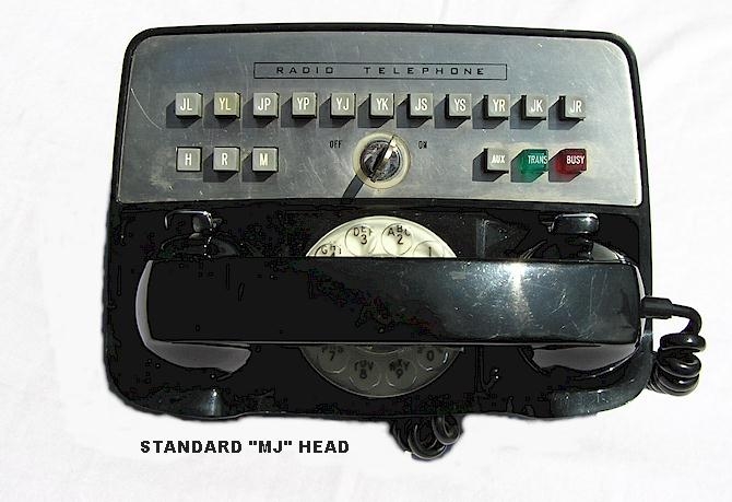
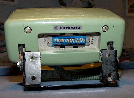
The MJ Standard Control Head
The MJ system employed a standard control head design, developed and manufactured by Secode, all of which were labeled ITT inside and then labeled with the appropriate manufacturer's logo on the outside faceplate, such as Motorola, GE, Bell System, left blank, or with a generic logo saying "Radio Telephone" (see example below.) The control head is interchangeable among all manufacturers of the equipment, even though the actual radio packages differ greatly. The cables for the assorted brands of "MJ" equipment are also all interchangeable, so that a GE head and cable will work perfectly on a Motorola RF package, and vice versa. The first AMPS cellular telephones featured the same scheme - - a control head from one manufacturer would work on almost any other manufacturer's radio package and cabling.
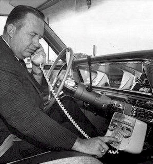
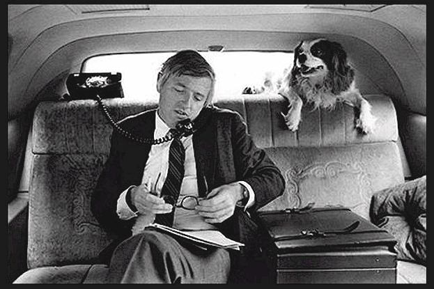
Note the photo below, which is dated July 8, 1962 and described thus:
New Type Auto Phone on Market. Dick Hyde, of Hyde Electronics, Denver, uses handset in car for long distance call while Ted Lursing, sales manager for International Telephone and Telegraph Company, looks on (out of view.)
However - - this photograph clearly shows a 1966 Chevrolet dashboard, not a 1962, and the photograph was somehow incorrectly dated by the news agency that took the photo. How this happened remains a mystery. Thanks to Tom Kopec for pointing this out!
GE also produced its own version of a control head for use in the MJ system, as shown in the GE IMTS section below, but this design post-dates the original MJ concept, and they are rare.
The MJ head is probably the most recognizable mobile telephone head of the 1964 -1980 period and can be seen in many TV shows of the era (such as Banacek, Hawaii Five-O, Ironside, etc.)
The example below is a generic MJ control head from a phone registered in California's Pacific Telephone system. The "revertive call" version would have had a "P" button for "party" in place of the "Aux" button. See the revertive call description below.
These heads were available in many colors. The most rare is probably the pink one. I occasionally wonder who ordered the pink head, if anyone.
Typical colors available were black, white (subject to yellowing today,) beige, gray, Bell Telephone green, red (rare,) powder blue and pink.
Note that the MJ control head also allows the radio to function as a traditional MTS car telephone by using the "M" (Manual) button. And that initially, many telephone companies supplied the heads with cardboard sleeves on the button shafts under the front panel so that neither the H or R buttons could be depressed. In this way, the phone operated as an MTS-only unit. For example, the California Pacific Telephone system did not convert to IMTS until 1982. At that time, shops "converted" the MJ radio-telephones to IMTS by removing the cardboard sleeves and resetting the mobile numbers to standard 7-digit IMTS style, which included the area code. In some cases, where roaming was not needed or desired, the cardboard sleeves were also placed under the channel buttons for those channels not installed.
Also note that the key, a 2252 Chicago double-sided type, is not the same as the key which releases the trunk-mounted radio unit from its tray (or housing.)
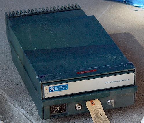
The Motorola MJ IMTS Radio
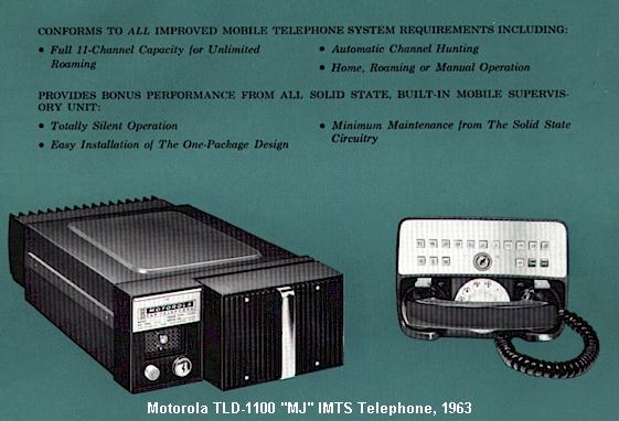
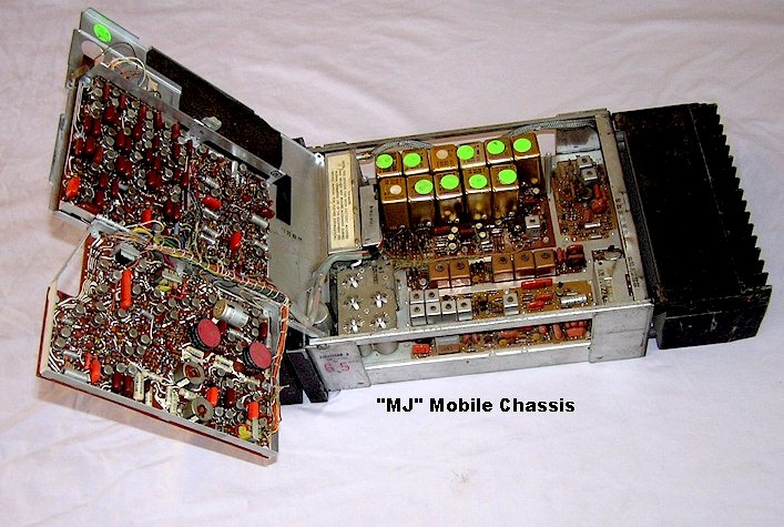
The MJ radiotelephone is a standard TLD1000 MTS radio, but with a change to the selective call decoder assembly. In the TLD1000, this was a simple MTS decoder only, located on a hinged bracket underneath the radio chassis. In the MJ TLD-1100 radio, the decoder was part of a "supervisory package" located in a large swing-out chassis consisting of several circuit boards located above the radio chassis. The MJ supervisory chassis consists of the circuitry needed to scan channels seeking the marked-idle tone, outbound dial signaling, initiate and hang-up sequences, and automatic mobile identification. All MJ supervisory chassis also have full MTS signaling capabilities for manual system use. A few MJ "type" supervisory chassis were supplied with a proprietary Secode interrupted 2805 Hz tone signaling format for the "Manual" mode instead of the Bell System's standard MTS tones.
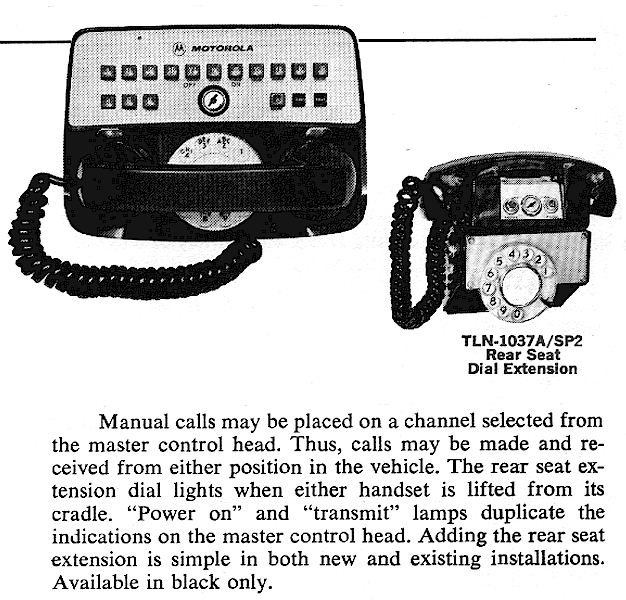
The MJ was by far the most popular and common mobile telephone, made by the thousands. A TLD-1000 MTS radio could be converted to an MJ radio by replacing the supervisory selector chassis and the control head, although this did not seem to occur often and some early TLD1000's were missing the necessary chassis connector assembly and required extra work. Both the TLD-1000 and the TLD-1100 offered limousine rear-seat extension phones. The TLD-1000 MTS rear seat extension was a compact, attractive plastic unit resembling the older 47E series MTS control heads, but did not feature the ability to change channels. The IMTS rear seat extension was a rather crude and ugly-looking affair which evidently was pasted together in a great hurry, and few were sold. The IMTS rear seat extension allowed dialing but not home/roam/manual selection or channel selection. An optional version featured a "Party" switch for revertive call operation (see below.)
The TLD-1220 was a TLD-1100 IMTS mobile which offered "revertive call" operation. Instead of the "Aux" button on the control head (which blew the car horn when the phone rang), there was a "P" button in its place. The "P" button stood for "Party" (party line), also called "Revertive" operation. The purpose of revertive call operation was to allow two mobile telephones to converse with each other on the same channel (push-to-talk operation only !) Pressing the "P" button would take the mobile transmitter off the air and put it into push-talk operation via the button on the handset (in IMTS operation, the transmitter normally stays on the air continuously during the duration of the call.) When one mobile called another in a "revertive" system, both the calling and the answering mobile would hear a special tone sent out by the central office (usually a string of "beeps"), or in some cases a recorded announcement saying to "press your "P" button." The tones or announcement were heard by the calling and answering mobile, because both had to comply. The central office station then acted as a conventional "repeater." The TLD-1100 units had no way of receiving a revertive call, although pressing the "M" (manual) button would bring the radio out of IMTS mode and into manual, allowing the call to proceed, but at the end of the call, the mobile would be unable to then send a disconnect tone in IMTS format, and it would be necessary to rely on the terminal to "time out" from the time the land party hung up, or from when the last carrier on the mobile input was heard, whichever occurred first. Most independent telephone company units seem to have been TLD-1220's, while most Bell System units were TLD-1100's.
MJ installation in my 1993 Ford: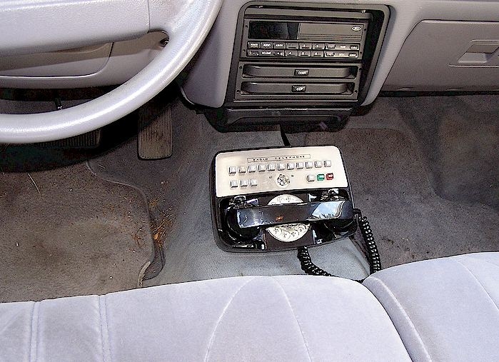
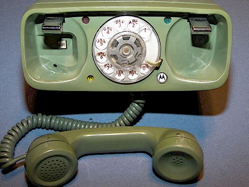
Rear Seat Extension
Motorola's MJ equipment could be special-ordered with a rear seat extension for limousines as shown below. Note that a revertive-call model was also offered, which featured a "Party" button next to the dial.
KEYS: I get inquiries regarding keys for the MJ radio heads and the radio drawers themselves. Please note that the key for all MJ, Pulsar I, FACTS and MK heads is the 2252 Chicago double-sided key. The radio itself uses the standard Motorola 2135 key. 2135's are available on eBay almost all the time and 2252's may be available there as well from time to time. The MTS heads use a different key and many are individually keyed. The Western Electric 41 and 47 series heads are individually keyed with a Yale key.
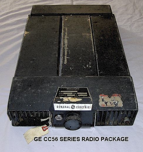
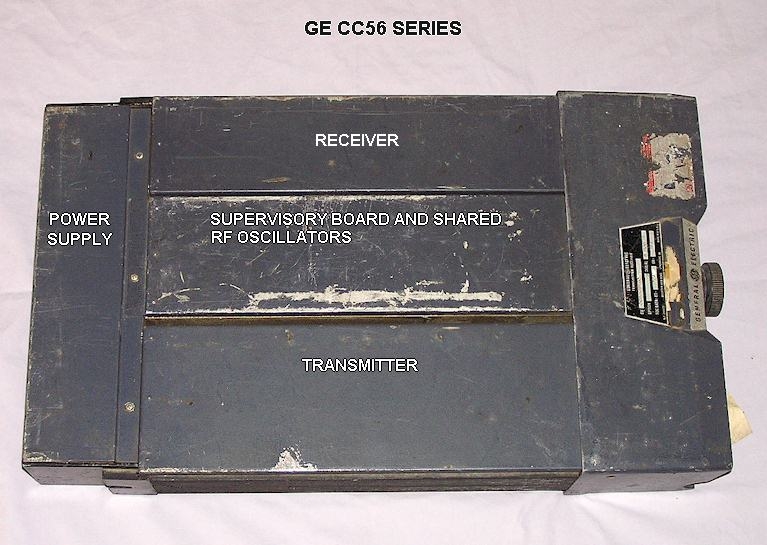
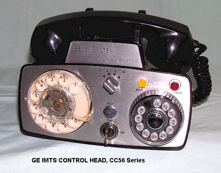
The GE MASTR CC56 IMTS Radio:
GE introduced an IMTS radiotelephone sometime in the late 1960's which provided the same features as Motorola's TLD-1100/1220 series, however in a somewhat cruder presentation with far greater size and weight. The CC56 was essentially a conventional 30 Watt MASTR Professional series mobile radio, except with the power supply mounted across the rear apron and a mobile selector - RF oscillator chassis in the center. The CC56 unit could be purchased with either an MTS/IMTS selector package (as the Motorola MJ radio,) a "Dial" selector unit, compatible with the "Dial" and "Identified Dial" systems already in use with GE Progress Line DTD series equipment, or only an MTS decoder.
The CC56 in the IMTS version could be supplied either with an "MJ" control head as used in the Motorola equipment, shown above, or a GE proprietary head (see photo below.) The GE CC56 was discontinued sometime in the mid 1970's, and was replaced with the MASTR Executive II equipment. The IMTS CC56 was shipped with an interesting version of the GE MASTR Professional receiver which had one extra helical resonator in the "front end" compared to the standard MASTR mobile radios.
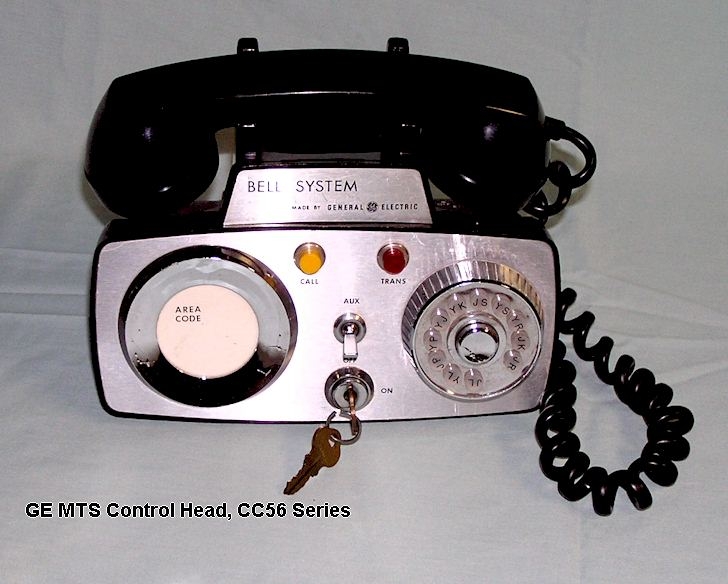
The CC56 mobile was also shipped to Bell System operating companies which were still MTS and without plans to modernize to IMTS. In that case, the control head below was shipped with the equipment: Note that it could not be upgraded to function as an IMTS head. It appears that the same IMTS supervisory chassis was shipped in the CC56 "Manual" mobile as with the IMTS radio, however the head would have to be changed to the IMTS version before the IMTS features would function.
1968: UHF Introduced, The Motorola MK IMTS Radio
In 1968, a number of UHF IMTS systems went on the air in urban areas, at the same time that the FCC outlawed all wideband modulation older equipment on the UHF frequency range, as it had done on VHF in 1962. There were already a number of manual MTS UHF systems in operation in the larger urban areas as well, which had been placed in service in the late 1950's to relieve congestion on the VHF channels, typically using GE Progress Line UHF equipment in the Manual mode. Motorola was already producing a fully solid state 12 channel UHF mobile radio called the MK XII (Mark 12), sometimes called the Motran Mark 12, which, with some modifications, became the T-1414 Duplex "MK" UHF radio. The MK system was merely a UHF IMTS format identical to the VHF IMTS system except that there was no "Manual" operation capability. The system was fully automatic, direct dialing without operator assistance needed. The MK radio came with the "MK" control head. The MK control head eliminated the channel selection buttons or switches as well as the "Manual" push-to-talk mode, but otherwise provided the same features as the MJ equipment. The MK radiotelephone used the same supervisory signaling package as the TLD-1100 "MJ" sets. Roaming was available but via an internally strapped jumper matrix, programmed ahead of time. The user could not change the Roam channel list himself.
At some point during production of the MK control heads, an optional "add-on" top section was added which allowed user selection of Roam and (apparently) Manual channels, although there would have been some difficulty using it in a "manual" system unless the handset was replaced with a push-to-talk model as well. These pieces are very rare and apparently did not see widespread use other than in large metro areas such as New York City and Chicago, and possibly in telephone company vehicles only.
By the 1970's, there were control heads available for MK radios as shown below, but with pushbutton Touch-Tone® keypads in place of the rotary dial. These were primarily useful in the urban, non-roaming environments the MK radio was intended for. Not all systems would recognize the DTMF tones from such keypads.
Photo courtesy of Steven Scher, Bronx NY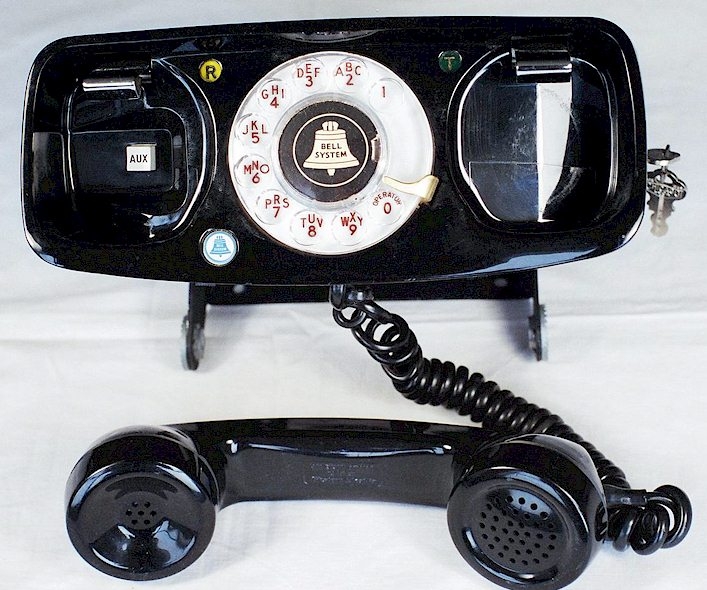
Green MK Head:
MOTOROLA UHF "MK" RADIO, T1414
MK control head mounted in unusual location (Recognize this guy?) :
Like the TLD1100 "MJ" equipment, the "MK" equipment used no moving parts (i.e. relays or stepper switches). The supervisory board assembly is the same as in the TLD-1100 and TLD-1220 "MJ" mobiles. The MK receiver was surprisingly sensitive for its day, and the transmitter matched the power output generally available from VHF radios, doing so via a varactor tripler which required delicate and extensive filtering and tuning in the transmitter output stage. The MK transmitter filter and tripler assembly was considered so complicated and sensitive to align that Motorola recommended they be returned to the factory should any adjustment or repairs be needed. This was before the era of widespread availability of RF spectrum analyzers in radio shops.
The original MK equipment leased by the Bell System was replaced in the mid to late 1970's by the "UHF Pulsar" radio drawer which would later be referred to as "Pulsar II" equipment. The MK has a rather peculiar, complex and expensive to manufacture housing and tray assembly not used on any other model. The example above is a former test unit from AT&T Labs in New Jersey. Customer owned MK equipment continued in use until the end of service.
It appears that GE did not offer a UHF IMTS mobile telephone until the Executive II style in the mid or late 1970's, which is odd, since UHF versions of the MASTR Professional mobile were made for years, and it would seem a simple matter to have combined those chassis into a UHF "CC56 style" IMTS telephone with the same appearance as the VHF CC56 series. Harris RF offered the CT-450, in the mid-1970's, which used any of the aftermarket control heads which contained IMTS signaling within the head itself.
UHF was cheaper in terms of monthly rental fees, but not particularly suited to users who traveled out of town. It was much less popular in the western states and UHF IMTS equipment is rare.
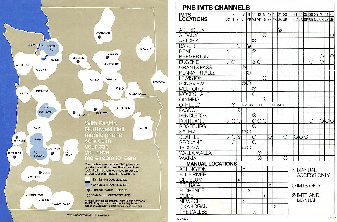
THE CHANNEL GUIDES
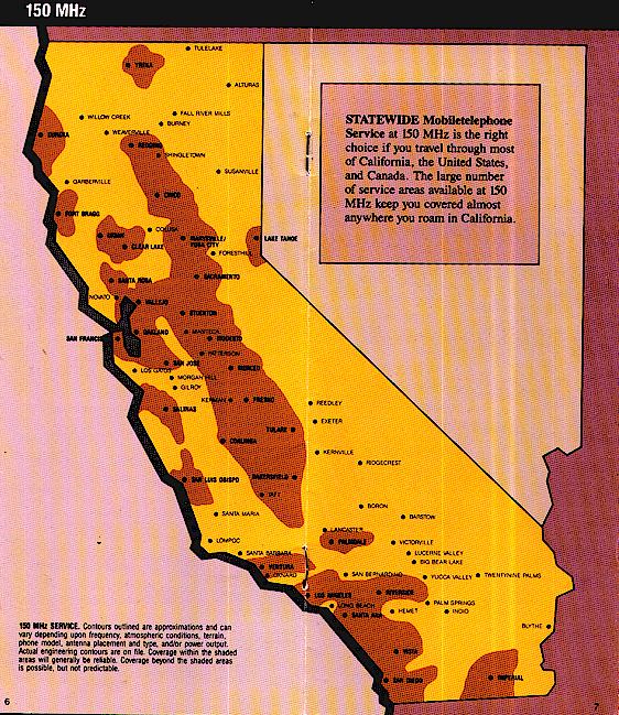
I have been asked how mobile phone owners knew which channels to use, depending where you were. In their home city, the telephone company told them. These were the "Home" channels and should have been pre-programmed into the MJ control heads as shown above so that when the control head was in the "H" mode it was automatically set to scan those channels only. When traveling away from home, the owner would refer to a channel guide provided by his telephone company. This guide consisted of a map showing coverage in various cities served by his telephone company, and a chart showing which channels were used, and where. As mentioned elsewhere, IMTS, despite being introduced in 1964, was very slow to be adopted and many cities into the 1980's had both Manual and IMTS service simultaneously, while a few were still manual and a number of independents were still Dial or Identified Dial (GE - Secode equipment only.)
The pages below show such a map from Pacific Northwest Bell in the early 1970's. This chart and map do not show the independent company systems, for example Whidbey Telephone Company on Whidbey Island. Other Bell operating company maps grudgingly did show independent company channels and coverage , usually with assorted notes about those systems being "foreign" or "roamers not allowed."
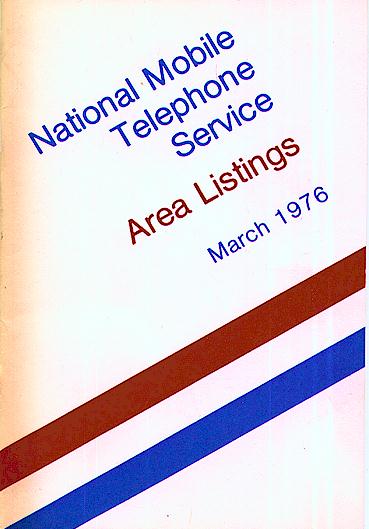
The local phone companies only printed maps and guides to systems they maintained. There was also, at least in the 1970's, a booklet .published by AT&T entitled "National Mobile Telephone Service Area Listings" which covered all fifty states and did list the independent systems as well. It appears these booklets were updated twice a year as I have issues dated September, 1974, March 1975, September 1975, March, 1976 and Spring, 1982. It appears that by the 1980's the editions changed to spring and summer. This ended with the divestiture of AT&T in 1982, the last one published was apparently the Spring, 1982 edition. If you have editions of these small booklets other than the ones I have, I would like to have them (or copies) for eventual addition here.
Following the AT&T divestiture, in the mid 1980's a private firm in Mercer Island, Washington, Communications Publishing, began selling a nationwide channel guide booklet to fill the gap left by AT&T's cessation of publication. This book was much more comprehensive and much larger than the AT&T version and contained information on the addresses and contact numbers for all the assorted telephone companies, including independents, so that roaming or secondary service could be established. Cellular was in its infancy at that time, and Communications Publishing also sold a booklet for Cellular roamers. That book of course did not list frequencies or channels, but mainly roaming processes and whom to contact depending on where you were at the time (cellular seamless roaming was non-existent at that time.) The Communications Publishing booklet was the last channel guide published for IMTS. It was normally kept in the car glove box.
Examples of local company channel guides and maps:
The AT&T National Mobile Telephone Service booklet:
The Communications Publishing channel guide booklet, 1987:
[Photo follows soon]
Ver. 7/18/2020 © 2005 Geoffrey C. Fors All rights reserved