MYSTERY RADIO GEAR
Page Three
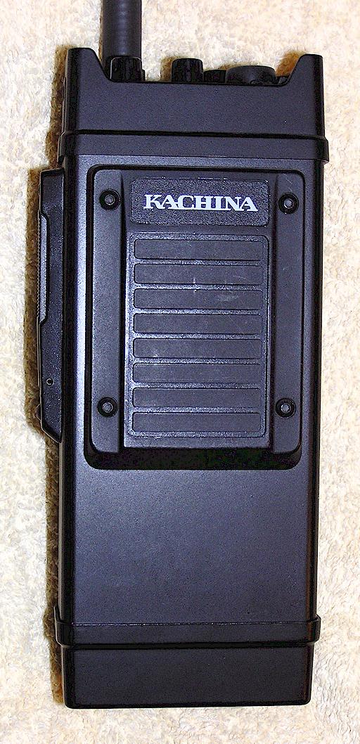
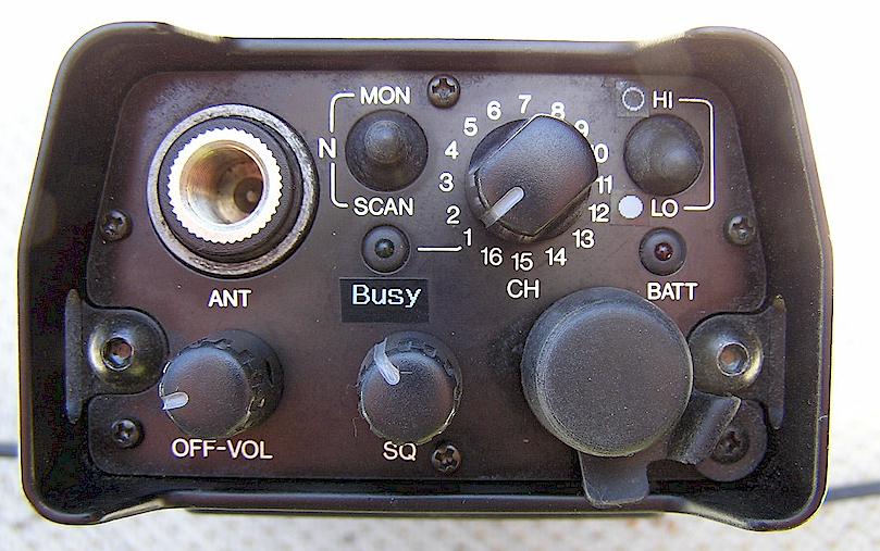
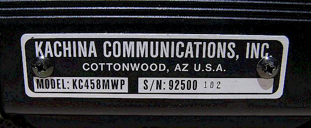
KACHINA ORPHAN LOW BAND MILITARY HANDHELD
Another not-really-a-mystery radio, this is a brand new 1990's Kachina Communications 66-88 MHz hand-held FM transceiver made for military sales. Kachina went out of the radio business some years ago, making this an orphan. I was unable to find out any data on it. 16 channels, hi-lo power, scan and (apparently) a CTCSS function. Built stronger than a brick in an anodized aluminum case.
Click below for a pdf copy of the Kachina brochure for this radio and also the MP-25 man-pack SSB radio.
Dial-up warning - this is a 7 Mb download!
Courtesy Bruce Haffner, WD9GHK
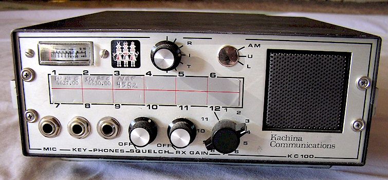
KACHINA KC 100 HF SSB TRANSCEIVER
Yet another not-really-a-mystery item is the Kachina KC 100, a high frequency SSB transceiver which I have been told is similar to the ALDA 103 amateur radio. It puts out about 150 Watts PEP. Most of these seem to have been utilized by the Civil Air Patrol. Evidently there was an optional provision for AM and LSB, although all of these I have ever seen have been USB with a plug button in the mode switch hole as shown in the photo below. Kachina made a series of HF SSB radios, apparently ending with the KC 105, and then moved on to an interesting software defined radio that interfaced with a personal computer, before exiting the radio communications business about 2003. They no longer support this or any other radio item. The channel select knob is one from my junkbox and doesn't exactly match the original. I have heard that the Taliban used these radios for a time in Afghanistan and Pakistan along with a variety of VHF and other HF tactical sets.
HALLICRAFTERS OPS/FM-5 - Vietnam Radio
This took less than an hour after I put the photos up, to be identified.
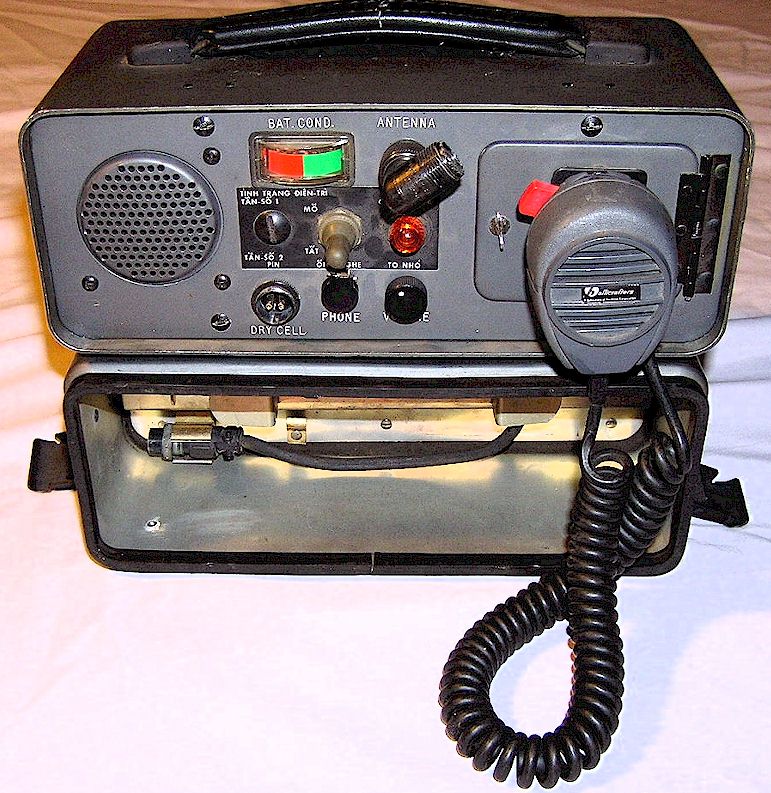
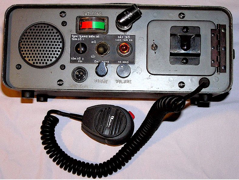
Thanks to Bruce Haffner, WD9GHK, it has been determined that this is a Hallicrafters OPS/FM-5 VHF FM radio, which, based on the Vietnamese panel, must have played some part in the Village and Hamlet Radio System in Vietnam in the late 1960's. It may actually be an OPS/FM-5B. If you can shed some light on the exact differences between the FM-5, A, B, and any other suffix, please share it! Motorola made a clone of this radio and possibly Hammarlund did as well. Originally, there should have been a nameplate under the speaker, in the form of a metal foil sticker. This one has none.
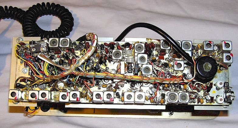
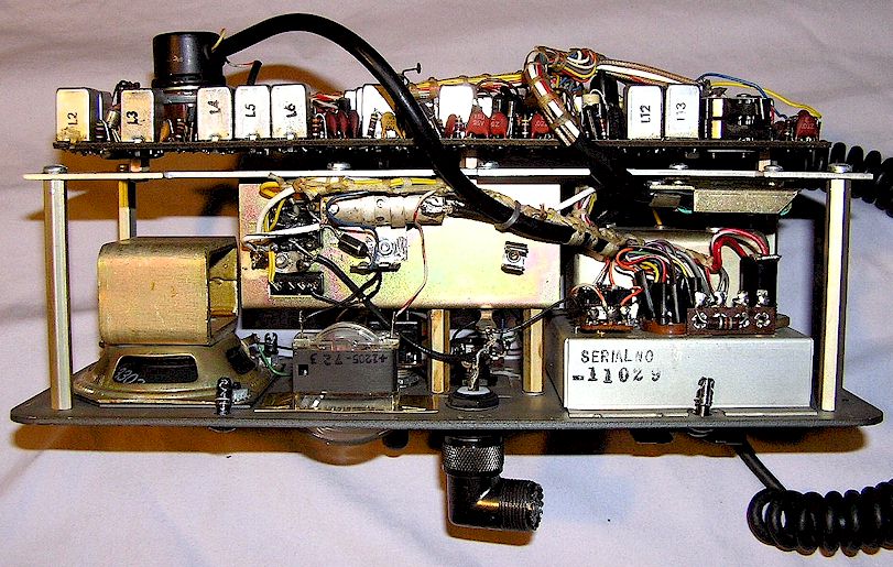
This one still has crystals on a 153 MHz frequency. The frequency range is about 150-163 MHz. There is a dual micro-switch inside which can be manually closed, labeled "repeat," which would allow two of these radios to be connected together as a repeater. As can be seen from the photos, this set is basically the OPS/FM-1 hand-held radio's circuit board placed inside a larger cabinet with speaker, metering, RF PA for the transmitter and some other options. There is a metering test-set socket behind the door along with some adjustment access holes and additional test points. This one only has provisions for one channel although the crystal sockets and circuitry are already in place on the board for a second channel, and all that would be necessary would be to add the switch. There were many options for this set, such as an add-on RF power amplifier, power supplies, repeater kits, larger base station antennas and so forth. It would be interesting to learn how many of these actually made their way to Vietnam and were put to use, if any did.
There is a manual available on the web as a pdf which is the Office of Public Safety version which also covers the FM-1. There was also a rather detailed Hallicrafters manual. These will tune up on 2 Meters with the right crystals, but a CTCSS "PL Tone" module would need to be added, such as a Com-Spec SS-32, as most ham repeaters require a CTCSS tone these days.
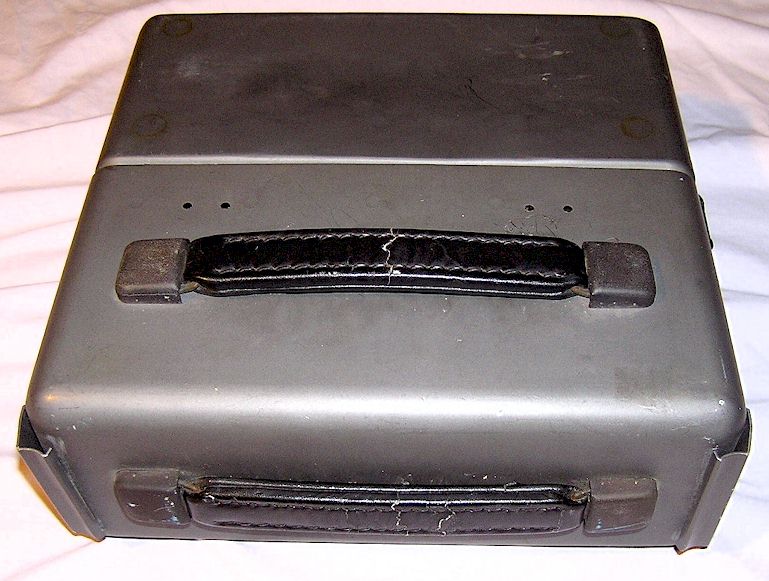
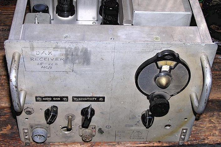
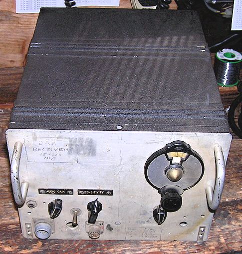
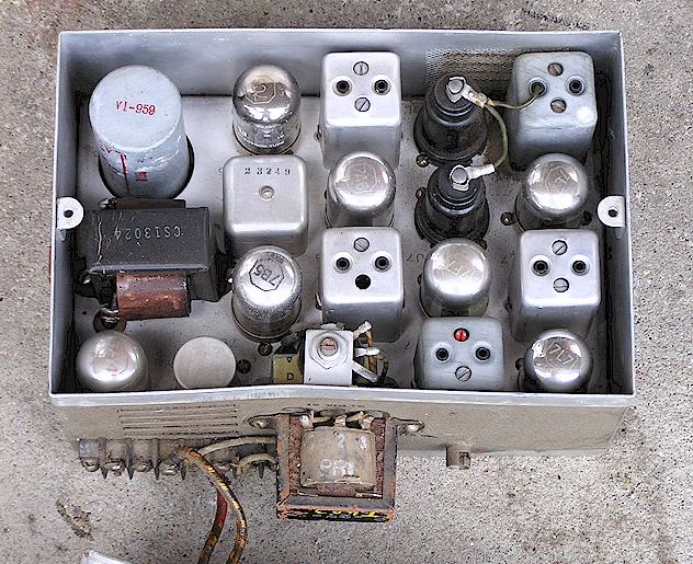
THE STRANGE CASE OF THE DAX RECEIVER
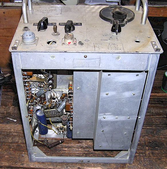
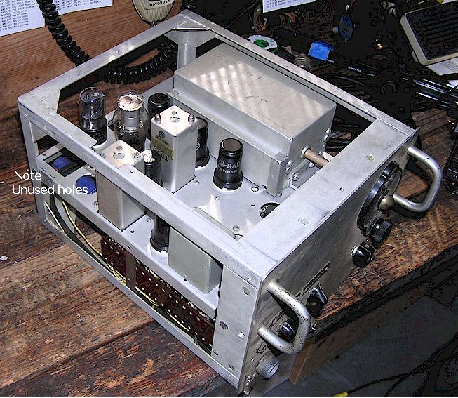
Truly a mystery is this receiver I rescued from an estate load at the old "Foothill" electronics flea market when it was briefly held in the Lockheed parking lot in Sunnyvale, California in September, 2004. The DAX was a rather obscure mobile naval DF receiver from the 1944 era, however this one appears to have possibly been a factory prototype, The front panel is rather crude with letting done in pencil. The chassis is obviously hand made, but with a high degree of precision which would seem unavailable to a home constructor. There are complex castings which would have had to have been made in a manufacturing plant. The wiring quality ranges from the superb to rather crude, perhaps representing successive work on the set. The receiver is an AC-DC transformerless design operating from 120 Volts. I have it in functional condition, however a number of aspects leave a lot to be desired. There is no BFO, and the tuning on the uppermost band is far too fast and the stations crowded together. The set has no AGC. The lowest band can be driven into overload by strong signals with a modest antenna. The antenna connection is via the rare "twin" SO-239-style connector. The empty hole next to it was possibly for a "sense" antenna. I am looking for a DAX manual to compare circuitry. Let me know if you have one!
So...what was this? A design prototype? A damaged DAX which was completed by some ham? A homebrew job made with leftover parts from the DAX production line? The answer may remain a mystery...
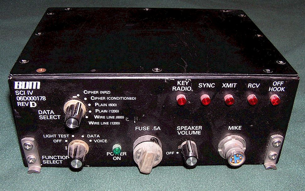
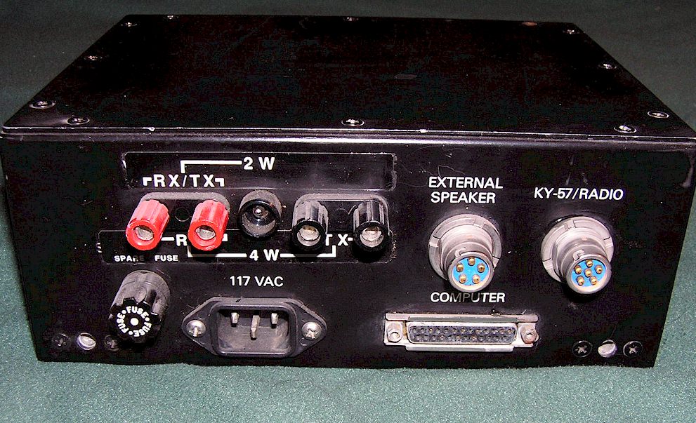
BDM SCI IV
This appears to be some sort of modem for use with late model military cipher equipment. Any ID or data appreciated!
US FOREST SERVICE KU-R MEDIUM FREQUENCY RECEIVER
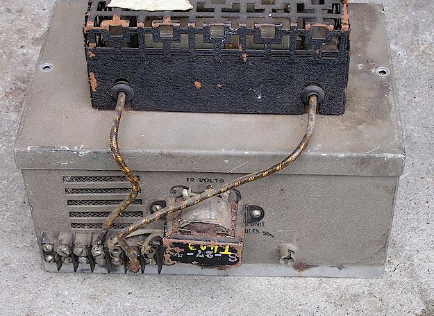
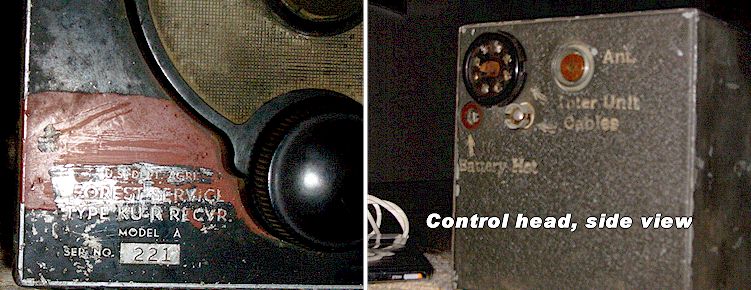
This was found at an electronics flea market in June 2009. No longer a mystery as of October, 2009, it was previously listed here as such and thought to have been a 1.7-2.5 MHz mobile police set. Thanks to Craig Leventhal, N3TPM, it has been identified as a Northern Radio Seattle Type KU-R Model A mobile receiver, made for the U.S. Forest Service probably around 1944. The main radio "box" is in fact only an IF strip and audio amplifier; the RF stages, tunable oscillator and mixer are inside the control head (!) and the RF signal is piped to this unit via a cable. Northern Radio was a Seattle, Washington manufacturer of marine and tactical radio equipment which is primarily known for its marine radios made in the 1970's, although they, along with Spokane Radio and Radio Specialty Mfg. made a number of sets for the United States Forest Service during the war years of 1940-45. The U.S. Forest Service designed most of its radio equipment in-house during these early years and some of it is a bit bizarre in appearance. In general, all USFS equipment prior to the conversion to VHF FM in the early 1950's is rare and was made in relatively small quantities.
The Cinch barrier-terminal strip on the example below appears to have been added later by someone, replacing the original, as was the external audio output transformer stuck on the exterior (evidently the original is defective.) There is a metal cage on top containing two power resistors to drop the input voltage, in this case from 12 Volts to 6, the original primary input power. The old auto-radio style bayonet fitting is not the antenna input, as I originally believed, but actually the IF signal input from the control head.
Photos below show the
original control head, courtesy Craig Leventhal, N3TPM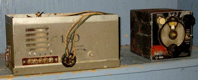
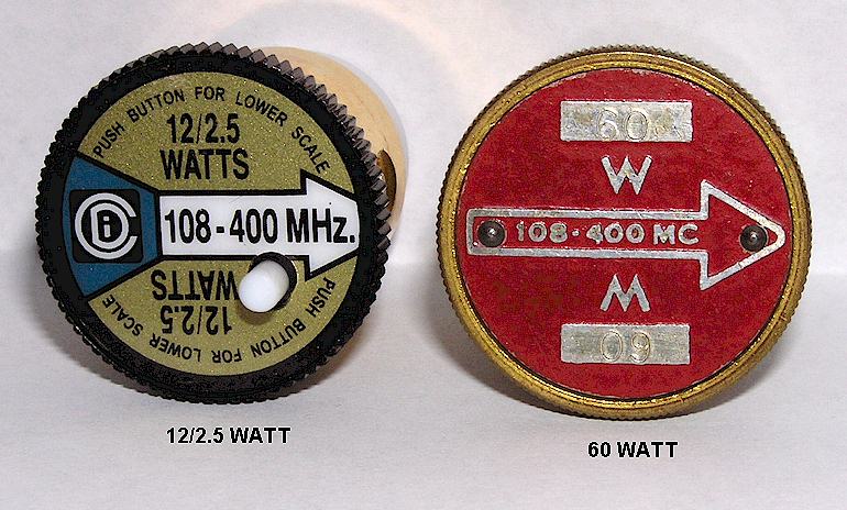
"WRONG" BIRD STYLE RF WATTMETER ELEMENTS
What's wrong with the wattmeter elements below? They are made for a full scale reading which doesn't exist on off the shelf Bird, Sola Dielectric or Coaxial Dynamics RF watt meters! What are these for, and why? The Coaxial Dynamics element on the left and the Bird on the right are from the FAA. There were some wattmeters with a 12.5/ 2.5/25/60 Watt scale, with a larger plastic faced meter, which these went with. None of the red-faced elements have a standard scale and all seem to be for this wattmeter. I have an FAA surplus Sola Dielectric wattmeter, yet it uses the same scale as a standard Bird 43, and can't use these either!
Update 5/6/2010 - Mystery solved! Thanks to Glenn Müller, N2CJ, who pointed out that Bird made a special version of the 43 Wattmeter for the Department of Commerce, FAA, with 60, 12 and 25 Watt full scales for use with these elements. The meter face appears to be plastic and is fully exposed, and below the meter there is a warning, in engraved red letters: USE ONLY ELEMENTS WITH RED PLATES . That explains where they came from, but one has to wonder why they specified different full scale ranges from the usual types unless they didn't want their wattmeter elements disappearing from stock.
Update 2/9/2023: Charlie, W4MEC offered the answer on these elements:
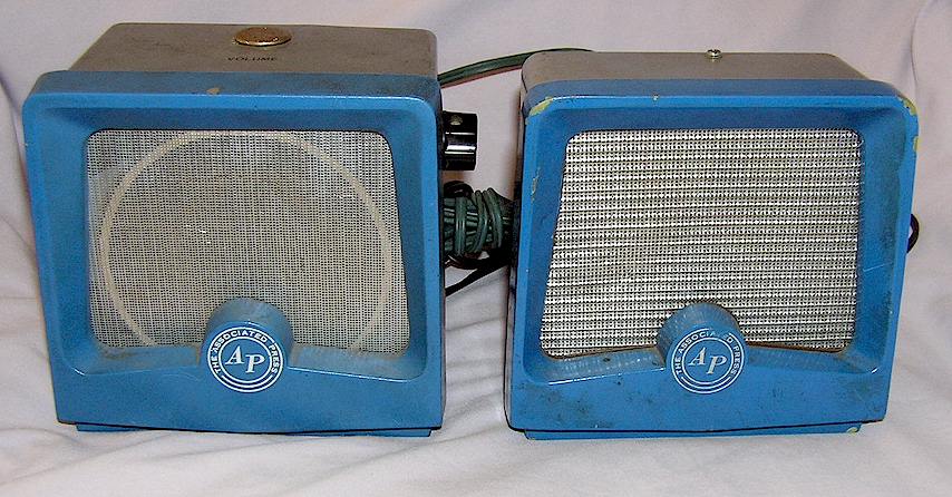
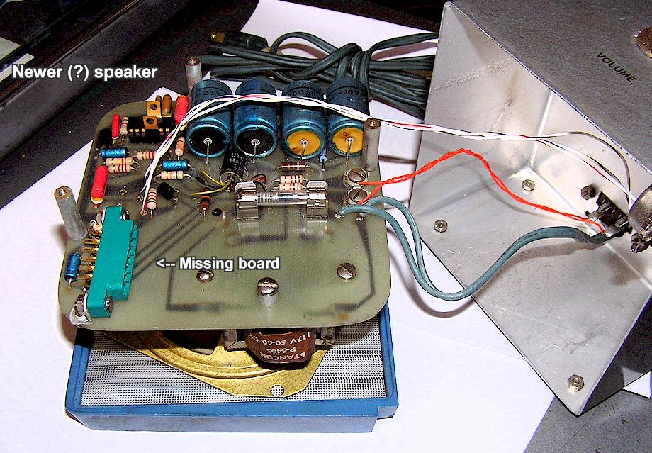
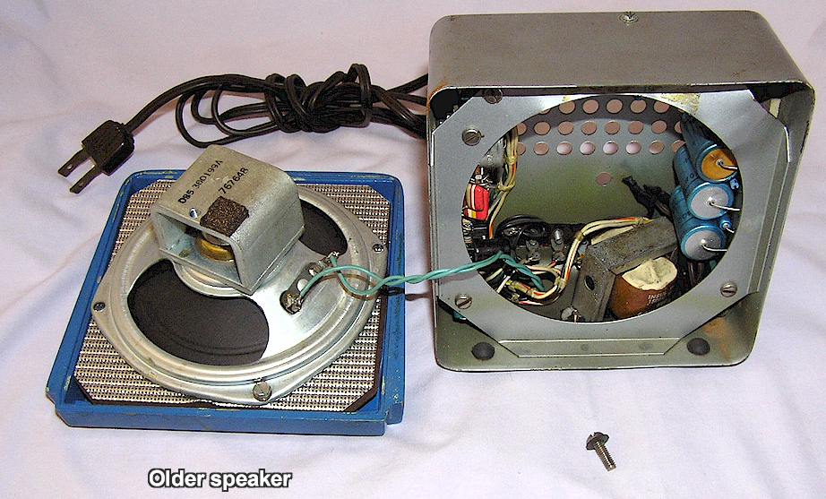
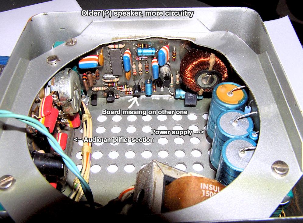
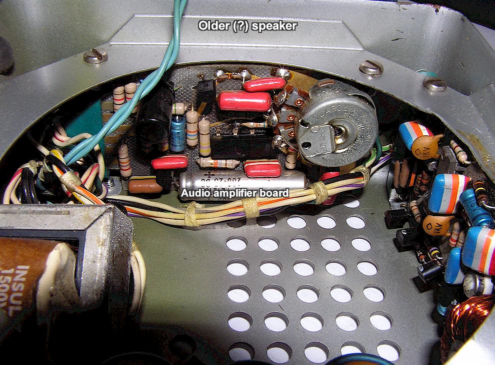
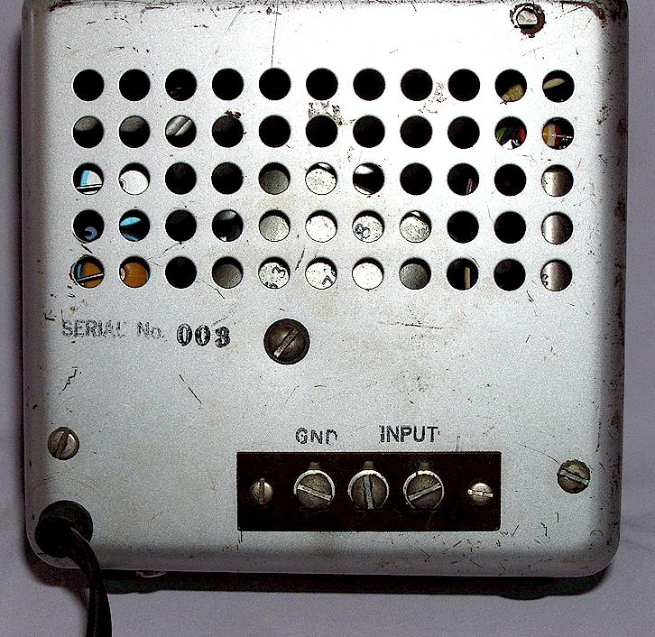
INTERNATIONAL SCANATRON SYSTEMS - ASSOCIATED PRESS (AP) SPEAKERS
These are a strange item found on eBay in May, 2014. They look just like the Hallicrafters R-48 speaker, except they are painted blue on the front trim bezel and have the "Associated Press" logo where the Hallicrafters one is otherwise. Inside, there is a lot of circuitry which appears to be a telephone line amplifier and audio stage. Friend David J. Goodman, WA8UIT, tells me he thinks these were used for wire photo machines on leased lines which also allowed voice traffic before and after transmission. If you know anything about these, it would be great to hear from you. These have tags which say
International Scanatron Systems Corp. , 1623 -Straight Path, Wyandanch, NY 11798
Contact me: geoff @wb6nvh.com
Ver. 2/9/2023 © 2008, All rights reserved