General Electric
FM MOBILE RADIO HISTORY
Part One, 1940 - 1965
NOTE: An excellent web page that also covers GE mobile radio history, especially the early years, is found here: https://www.gemradioha.org/
Introduction, Prewar Equipment
General Electric was an already well established manufacturer of a broad spectrum of electrical and electronic material when it decided to enter the land mobile (police) radio market in 1931. GE's initial land mobile radio products were mobile, station and motorcycle receivers for the AM medium frequency police channels in the 1700 and 2400 KHz bands, although I do not have reference material as to the models and other data. In the early 1930's the company branched out with an experimental VHF AM two way set, using a super-regenerative receiver, but which was more or less a toy rather than a serious police tool.
Inevitably, there will be "holes" in data coverage in any project like this, and I do not have enough information, manuals or examples of equipment to make this page an absolutely complete reference. For example, I do not have photos or detailed descriptions of the motorcycle and mobile equipment made by GE prior to 1940, other than that below, so while mentioned here, it is not covered in any detail. Equally unfortunate is that I have little information on GE's line of medium frequency and VHF AM equipment built prior to 1945, hence it is not covered here other than the 2-way item directly below.
1930's VHF 2-WAY AM
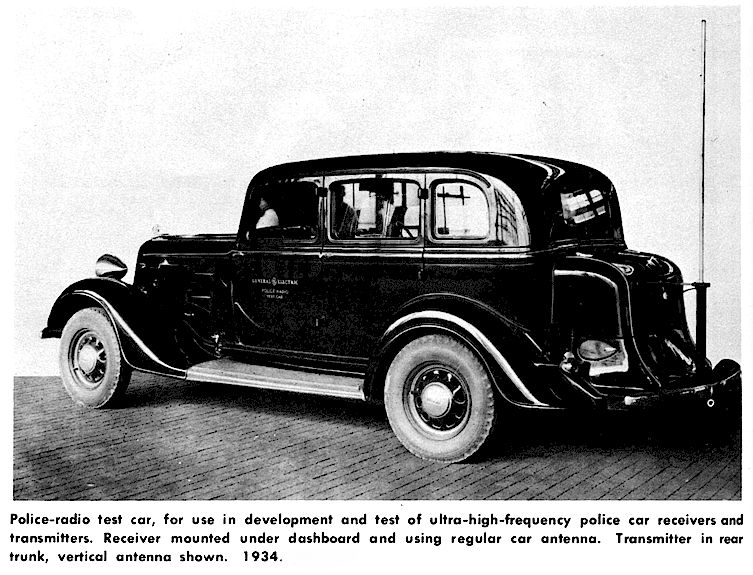
1934: GE installed its first two-way AM equipment in 1934 for the Boston Police Department, operating in the 30 Megacycle band with an experimental license. This equipment was built and designed at the GE Schenectady plant. The base station transmitter was a 1.5 KW (!) unit installed at Boston Police headquarters. Neither the receiver or transmitter nomenclature is mentioned in available materials.
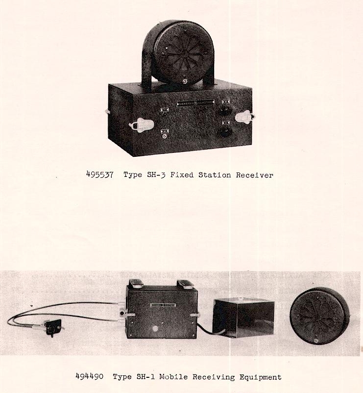
1936: Another receiver, referred to as the Model 4SH1A1 (mobile) or 4SH3A1 (station) is referenced in a manual published in 1936, which may have been an early model of the 1938 equipment shown below or the same model used in 1934 (above.) These were VHF AM receivers, superheterodyne, using 6 tubes and a separate dynamotor power supply,
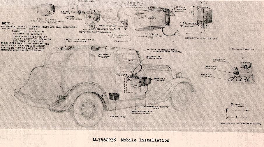
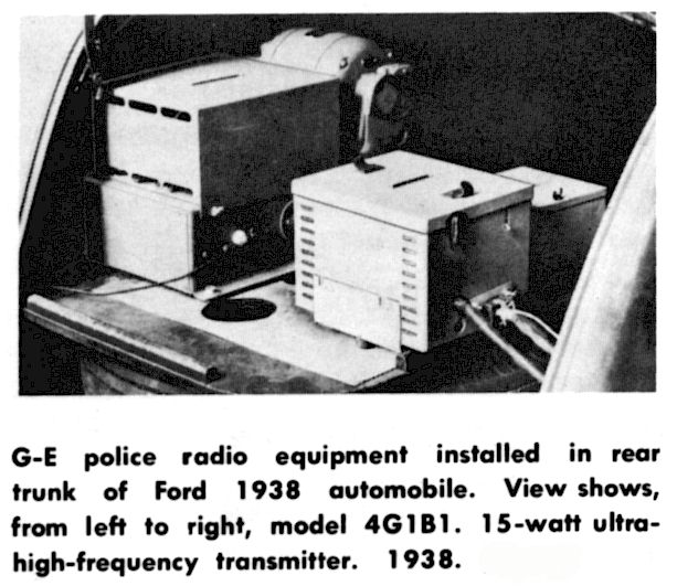
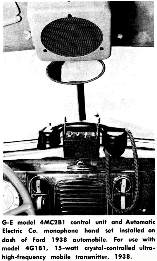
1938: From 1934 until the end of the 1930's, GE produced a 2-way VHF AM mobile radio. This was GE's last AM VHF two-way police radio, as far as I have been able to determine, and the outbreak of war in 1941 probably ended production of this model, which was quite obsolete by that time. Note the huge dynamotor which GE referred to as an advantage because it offered "continuous duty transmitter operation." It should be noted that equipment like this placed a huge drain on 6 Volt car batteries and electrical systems, often requiring changing of batteries at the end of each shift! The Leece-Neville "flux-cutter" alternator was marketed at the end of the war as a solution to the issue, allowing high current output even at idle.
THE SWITCH TO FM PRODUCTION AFTER 1940
In 1940, a revolution occurred in the land mobile radio industry, namely that the successful installation of a large scale VHF FM two-way (actually called three-way, because of the two-channel transmitters) radio system by Fred M. Link and Daniel Noble for the Connecticut State Police proved its superiority over the older low frequency one-way AM broadcasts and AM in general. From that point on, all major manufacturers switched emphasis to VHF FM products and generally introduced no new-design AM equipment from that point onward. GE was no exception. This is not to say that AM equipment was not still being sold, just that purchasers were still buying models and designs dating from 1940, more or less. AM production by all major manufacturers stopped by 1950, other than by special order.
GE had already been building FM mobile equipment since 1938, well prior to Link and Noble's experiments, on a somewhat experimental basis, in coordination with Maj. Edwin Armstrong. Armstrong is usually referred to as the "inventor" of FM although at least one patent was taken out prior to 1910 describing FM transmission. Armstrong's patents, perhaps more correctly described, covered the first actual practical application of FM. GE had applied to the FCC for an experimental license for FM operation on 49 MHz which was granted on August 3, 1938.
GE ran comparison tests of AM vs. FM (at 15 kHz +/- deviation) on September 28-29, 1939, with Maj. Edwin Armstrong in attendance, for the FCC Emergency Service administration. One of the persons in attendance was Professor Daniel E. Noble of Connecticut State College.
A GE VHF FM two-way system was already in use by late spring, 1940, for the Douglas County, Nebraska Sheriff, consisting of a 250 Watt base station and a number of 25 Watt mobiles (see Radio-Craft, Sept. 1940 p. 137.). Link's "first" FM system would have been being installed at relatively the same time, and despite attempts to whitewash it, was essentially a copy of the GE design. The Link Connecticut State Police system was the first large system to make use of FM, but the claim that it was the first VHF FM system is open to interpretation. Link's first FM equipment consisted of a modified 8UA VHF AM receiver and 15UBX AM transmitter from 1938.
GE was one of the few manufacturers to respect the Armstrong's patents on FM, and took out licenses to use that system, as did Link. Motorola did not, and was involved in litigation with Armstrong and Armstrong's widow (who eventually prevailed) well into the 1960's.
The initial GE-made mass production model FM mobile employed GE's E-1-A and E-1-B, which were large separate transmitter and receiver units, similar in physical design to Link equipment. One reason the units remained separate, other than weight and size constraints, is that purchasers often wanted to add only a transmitter to an already existing medium wave AM receiver installation in an automobile (California Highway Patrol, for example.)
It should also be noted that within months of completion of the Link system for Connecticut, Noble had joined Motorola, Inc. and Motorola was producing a two piece VHF FM radio of their own called the "Deluxe" line, which not surprisingly, appeared very similar to the Link 1940 FM equipment.
By 1941, GE had already revised and superseded their initial FM equipment of 1938 at least four times, making it somewhat more compact and updating some of the circuitry. These changes were referred to as " M.O.," for "manufacturing order." It should be noted that the first through third M.O. of GE FM equipment were actually manufactured by the James Millen Co. of Malden. Mass. using designs created by GE engineers in Schenectady, N.Y..
It is somewhat unclear what the "Fourth M.O." equipment designation was, other than that it was the first equipment actually manufactured by GE, at their Bridgeport facility, beginning in 1941. That equipment is believed to be the E-1 Series shown below. It is unknown what the Millen-made equipment looked like or the model designations, but it was a small quantity order.
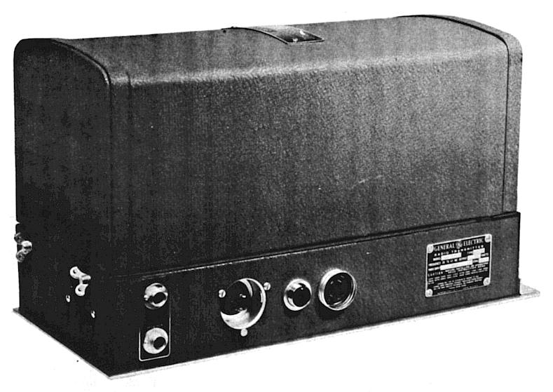
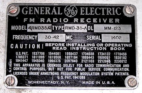
Following the E-1 Series, the next generation of equipment would have typical model numbers of 4RMD and 4TMD, referring to the receiver and transmitter respectively. This was the second generation of VHF FM radios produced by GE itself, and many were sold. They are recognized by the tall, rounded cabinet tops with a single handle in the middle. The transmitter was dynamotor powered and used an 807 tube in the power amplifier. The equipment was available only in the 30-40 MHz range. At this point the "M.O." designations become murky. The 4RMD and 4TMD sets may be the "5th M.O." equipment, but in any case there were "4th" through "7th" M.O. equipment produced up to 1949.
In 1942, production of "emergency equipment" (police radio) was moved from Bridgeport to the Schenectady works to accommodate war production, and GE's efforts were primarily directed to that area, and then to Syracuse by 1945.
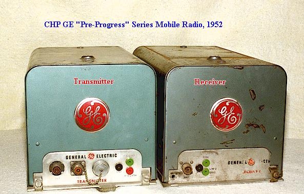
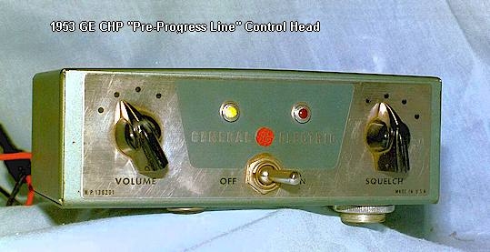
In approximately 1949, GE began production of a third and last generation of two-piece separate unit equipment, which saw large production figures and is the most recognized. This frosted-green colored equipment is usually referred to colloquially as the "Pre-Progress Line," because in 1955, GE introduced a highly successful series of radios called the Progress Line. The two-way radio industry then began calling the equipment which immediately preceded the "Progress Line" the "Pre-Progress Line," and even GE began to refer to it as such by the early 1960's.
GE insiders referred to the low band two-piece Pre-Progress radios as "8th MO," so apparently by the time these were designed, seven previous Manufacturing Orders had been completed of various styles and versions, as mentioned above.
In late 1954, GE began production of the enormously successful "Progress Line," a one-piece mobile radio made of interconnected chassis in a "basket" mounted inside a sturdy steel housing. The Progress Line would be made for ten years and was GE's flagship product. By 1959, the rush for solid state mobile radios caused GE to develop, perhaps prematurely, a radio called the "Transistorized Progress Line" or "TPL." These were generally regarded as a design failure with extremely poor reliability, and saw only a few years of production.
The Progress Line was made in a wide variation of models and combinations, and included portables (eventually), base stations, monitor receivers, railroad and so forth. Interestingly, there was no "Solocycle" (two wheel motorcycle) Progress equipment made, although a "Servicar" (three wheel motorcycle) combination was offered.
In late 1964, GE began production of the highly successful MASTR Progress Line, ceasing production of all previous models, and began a complete overhaul of the entire product line. GE from the late 1950's and onward also produced a secondary line of less featured "low cost" radios, including a dash mount VHF high band radio called the "Pacer" and a convertible-mount UHF radio called the "Accent 450." Both of which were essentially failures and reviled in the industry.
It is perhaps unfortunate that prior to the Progress Line, GE did not name the various equipment models. This makes it harder to refer to them in any convenient way.
Wartime and 1940's Equipment
From 1938 through 1949, there were eight different production orders of GE FM mobile VHF equipment, as shown below.
JAMES MILLEN 1st through 3rd M.O. Equipment, E-1-A, E-1-B through E-3 Series (1938-1941)
As mentioned above, from late 1938 through 1941, GE contracted with the James Millen Co, of Malden, Mass. to manufacture mobile VHF FM equipment to specifications drawn up at the GE Schenectady facility. Three separate orders were made to Millen during this time period, presumably "1st through third M.O. Durig 1930 and 1940 there was extensive experimentation among all the major radio companies regarding making VHF FM sets that would supersede the older AM VHF and "medium wave" dispatching AM systems.
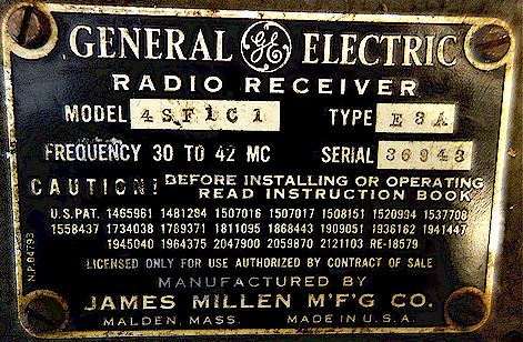
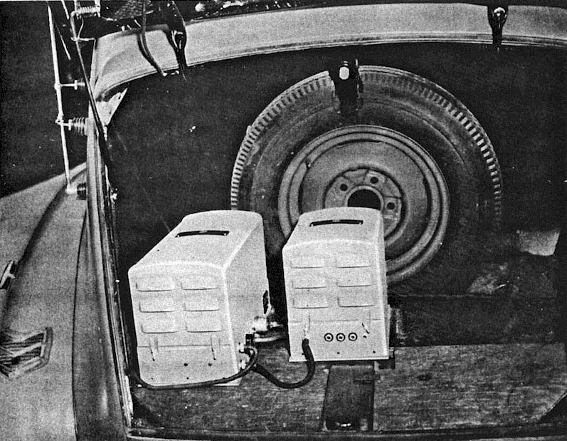
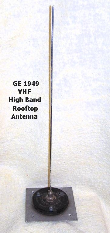
The E series radio equipment was most likely developed in late 1939 due to the new nature of FM, and was rather short lived, replaced rather rapidly by the RMD/TMD equipment described below in approximately late 1942. The basic E-1 mobile consisted of a 4GF-4 series transmitter and a 4SF-1 series receiver, both of which seem to have been made up to the -H suffix models. It was a 30 Watt 30-40 MHz FM set. The accessory set was the same as used by the RMD/TMD sets made later and as shown below. Note the peculiar "three-legged" antenna mount, probably supplied by Premax, similar to or the same as that used by Motorola during the same time period.
Thanks to Randy Liebermann for the above photo
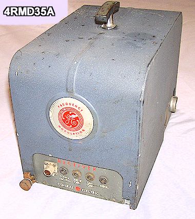
It is unknown if any of the E1 through E3 equipment was made in Schenectady by GE itself, rather than James Millen. The photo of the receiver below is not clear enough to read the nameplate, but it appears to be a GE nameplate without the James Millen lettering.
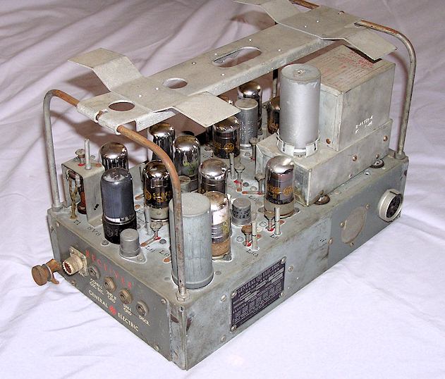
RMD/TMD Sets (1942-1949)
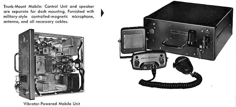
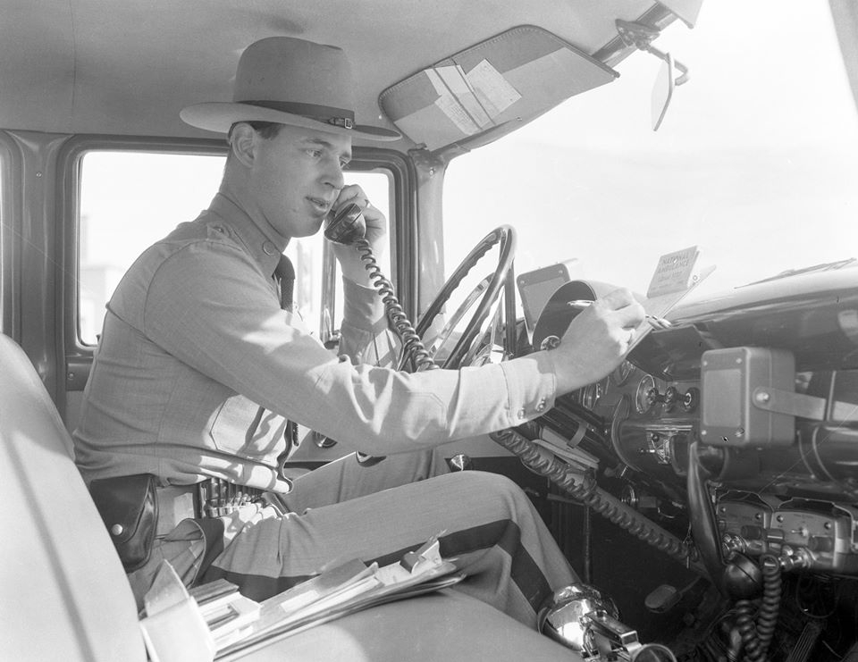
For lack of a better description, I have called this equipment the RMD/TMD model, referring to the part of the model numbers for each. This equipment was two piece in wrinkle-gray painted cabinets, recognizable by a large single "T" handle on top. See photos below. This model was introduced during wartime and was in production by late 1942.. The series probably included 4th through 7th M.O. equipment orders. It was replaced in approximately 1949 by the well known green colored "Pre-Progress Line" "8th M.O." mobiles discussed below. This equipment was produced only in low band VHF, and of course only in FM. The control head was very art-deco in appearance, as can be seen. It was available in 30 or 60 Watt versions, 30-40 MHz. The 30 Watt transmitter was the TMD-30, while the 60 watt was the TMD-60. These were made in large numbers compared to their predecessors mentioned above, and the green "Pre-Progress Line" "8th M.O." mobiles were essentially just upgraded versions of this design. Note that both these and their predecessor the E-1 sets were also available with internal AC power supplies to be used as tabletop base stations, in which case a box-like tabletop control box with internal speaker was supplied. Note also that the equipment was also available with a telephone style handset. The photo below is from 1943.
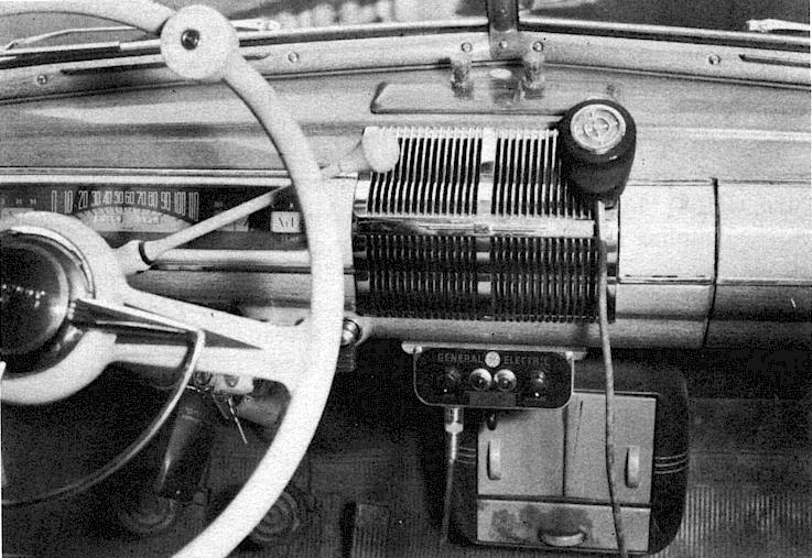
Note spinner knob on steering wheel!
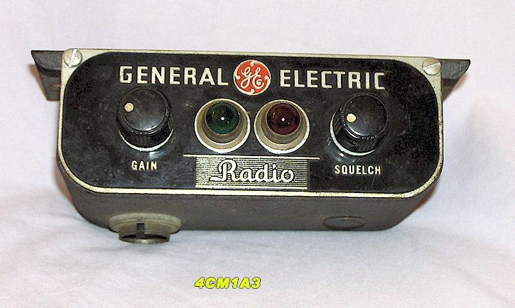
Below is the 4CM1 Series control head as used on both series. The speaker was usually a plain "bare" speaker cone attached behind the vehicle dash in the area where the entertainment radio would normally have gone (even into the 1960's, a car radio was a luxury option which added considerably to the cost of a new vehicle, and fleet cars would normally never have had one.)
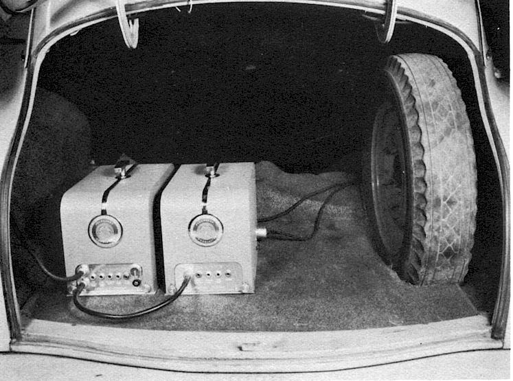
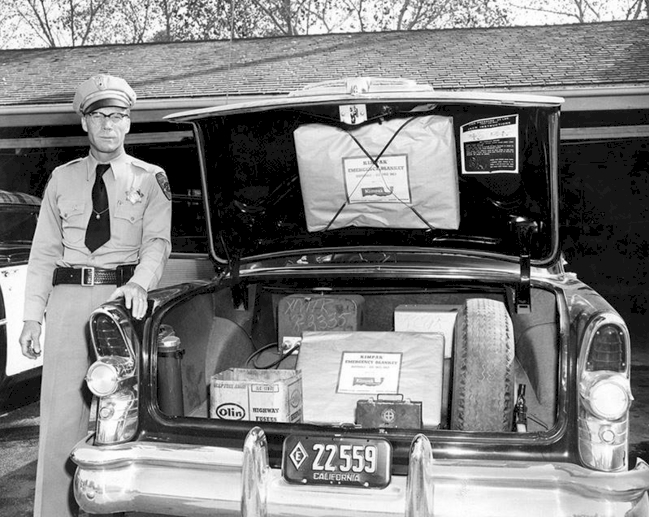
Shown below is a 4RMT-60 transmitter still in use in 1955 by the California Highway Patrol, a strange photo because this patrol car, a 1955 Buick, would have been in use well after the CHP system switched to all VHF FM operation on 42 MHz. Because there is no companion receiver in the trunk, this car must have still contained the under dash Motorola "Police Cruiser" medium frequency AM receiver abandoned in most parts of the state by 1950 and must have been taken at a very remote location which had not yet been switched over to VHF FM.
CARRIER CURRENT
In addition to the FM and AM equipment GE was manufacturing, there was also a great deal of interest in carrier current communications, or in other words, communications over electric power lines. Naturally this type of system was only used by the power utilities themselves, and generally, the signals only travel as far as the next transformer down the line, as they can not pass through the transformer. That being said, there were ways around this such as bypassing the transformer with high voltage low value capacitors to allow signals to pass. Carrier current was also used on non-energized lines by utility crews and some usage was made by railroads and subways in the years around World War II.
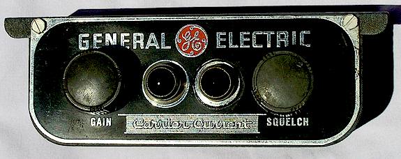
The control head below was recently found at a flea market as was somewhat of a surprise, as there was a Dymo label maker tape covering the area where the word "Radio" is on the control head above. Instead, when the label was removed, this one in fact says "Carrier Current." It is unknown what type of equipment was used with this head or how, although the REA power utility trucks during that era did make use of a system where the truck would have to stop next to an energized power line and deploy a long insulated stick with a glass insulator and blocking capacitor at the tip which would then allow communication with the utility station or substation as long as the truck was thus connected to the line. It's easy to see why that system fell out of favor; using it must have been a bit terrifying. If you know anything about GE's early "mobile" carrier current systems or have seen anything in print about it. do let me know.
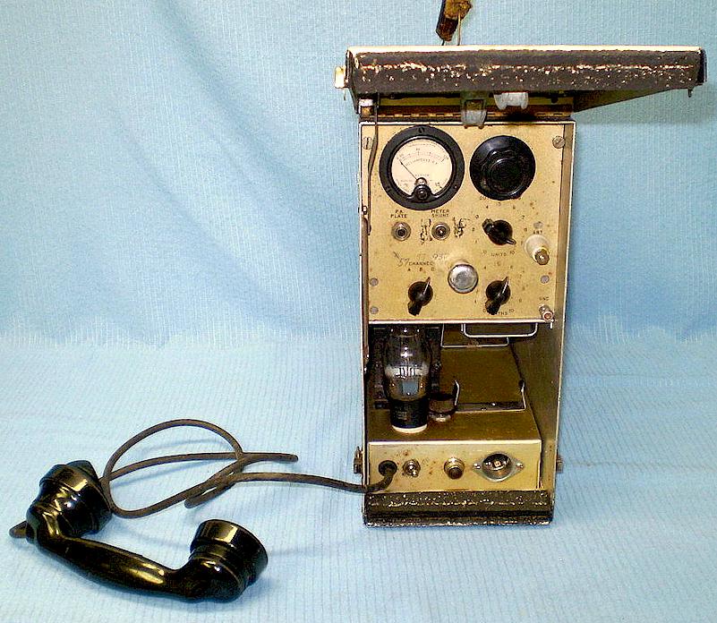
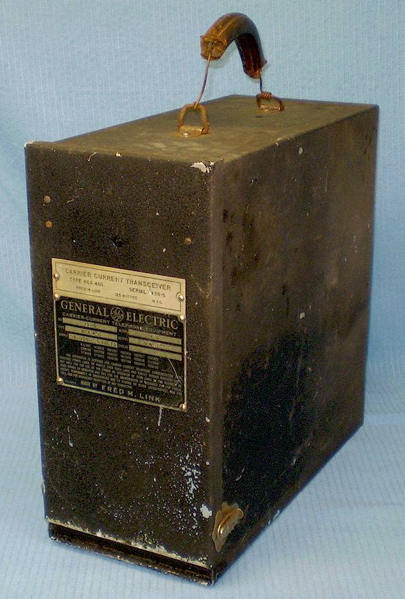
The interesting portable unit below was made by Fred Link in 1938 for GE and is a 5 Watt carrier current "transceiver" with three channels in the 97 kHz range. It was used by the Appalachian Power Company and somehow survived the decades.

Postwar Equipment, 1947-1955
Pre-Progress Low Band 2-Piece Equipment ("8th M.O." 1949-55)
By far the most common GE equipment prior to the Progress Line was the low band two-piece MC-1 series, specifically MC-1N and MC-1W ("N" referring to narrow band and "W" wide band.) This series is primarily recognizable by the green colored cases and the lack of handles on the case tops. The basic receiver chassis was also available in a rack mount base station configuration, as was the transmitter, with integral power supplies, but the chassis were not interchangeable between base and mobile as they would be in the later Progress Line equipment. These were reliable and highly successful radios which were slightly smaller than competitive Motorola equipment. The transmitter was powered by a large dynamotor and the receiver used a Mallory "Vibrapack" vibrator power pack. The equipment was available in either 6 or 12 volt versions, although as American automobiles did not switch to 12 Volts until at least 1956, the majority were shipped as 6 volt sets and converted later to 12. Presumably a military version was available in 24 volts. These are referred to as "8th MO" by GE insiders, and not "Pre-Progress Line," however by 1966 GE itself was calling these units "Pre-Progress Line."
There is evidence that GE produced MC-1 and MC-2N equipment in a 6/12 Volt version in 1953 (see McCormick's time line, above) although it is apparently very rare, since this equipment was discontinued by 1955 in favor of the Progress Line.
Photos of a typical Pre-Progress MC-1 set is shown below.
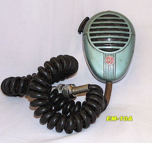
Note that the first generation EM-10 microphone above has a red "GE" logo below the grille; the Progress and possibly even later Pre-Progress microphones did away with this ornament and there is no GE logo on them.
The 4ER6 low band receiver, used in this set, underwent a constant series of revisions and changes, making it somewhat difficult for technicians to keep up with correct documentation. Most notable is that in the latest series of receivers, the method of volume control changed from a 4 ohm audio pad-switch arrangement in the control head (with the DC volume control mounted on the receiver chassis) to one where the DC volume control was located in the control head itself, and the hole for the DC volume control on the chassis of the receiver was left empty. This seems odd, since Motorola went the other direction as refinements occurred, placing the DC volume control on the chassis in later models, and placing an "L" pad for speaker level control in the control head, mainly so that audio decoder accessories could be used by accessing the high level audio available in the control head prior to the "L" pad volume control.
Because of the difference in volume control methods, control heads with volume level switches rather than potentiometers are early in vintage and will not operate with later model receivers, unless the receiver chassis is modified. Most heads seem to be the switch-style volume control.
GE publicized a number of tests in 1949-50 which showed this receiver as being superior to the Motorola Deluxe line set in terms of intermodulation distortion and adjacent channel rejection, although in fairness to Motorola, the Motorola Deluxe series consisted of 1940 and 1943 designs and had been superseded by the Research Line in 1950.
PRE-PROGRESS ONE PIECE EQUIPMENT (1947-1955)
GE occupied the new mobile radio headquarters facility in Electronics Park, Syracuse N.Y. in June, 1947. By August, 1951, GE's Kent Street plant in Utica N.Y. had become the new home of mobile radio production.
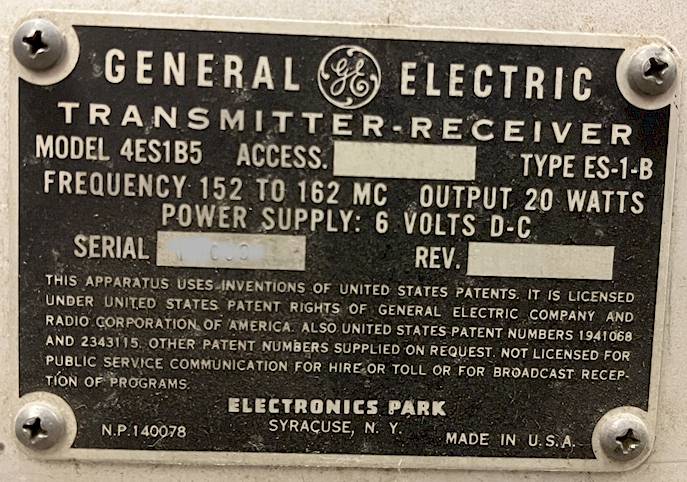
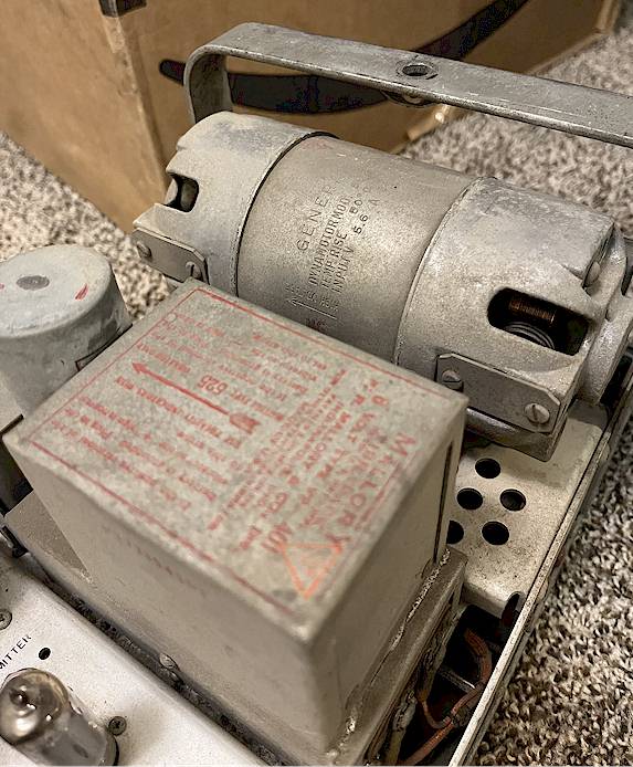
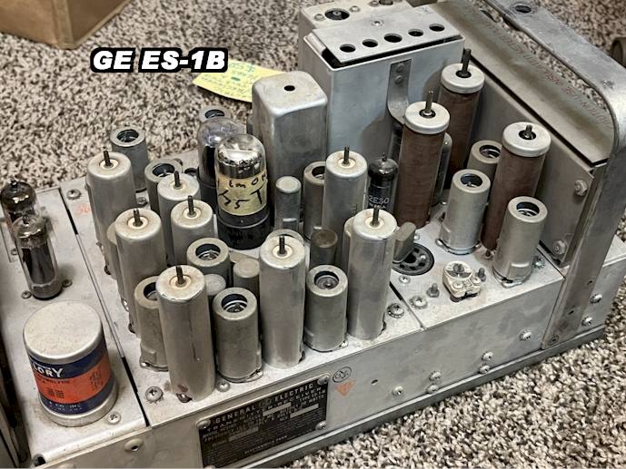
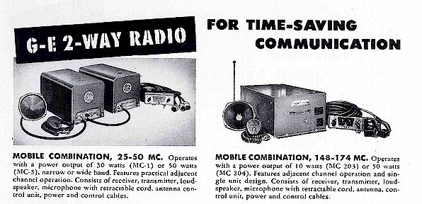
There were several model series of single-chassis Pre-Progress equipment. Primarily produced for VHF high band, two typical models were the ES-1B and the ES-12 (MC-203 and MC-213). The MC-203 was a square cased VHF high band low power (15W) radio set of approximately the same dimensions as the Motorola one piece lower power FM radios of the same period.
Both were vibrator powered mobiles, and seem to have principally seen service in taxis and small businesses where a power level of less than 20 Watts was ample. There was also a larger one-piece mobile containing both vibrator and dynamotor power supplies, however I have no photos or other information yet.
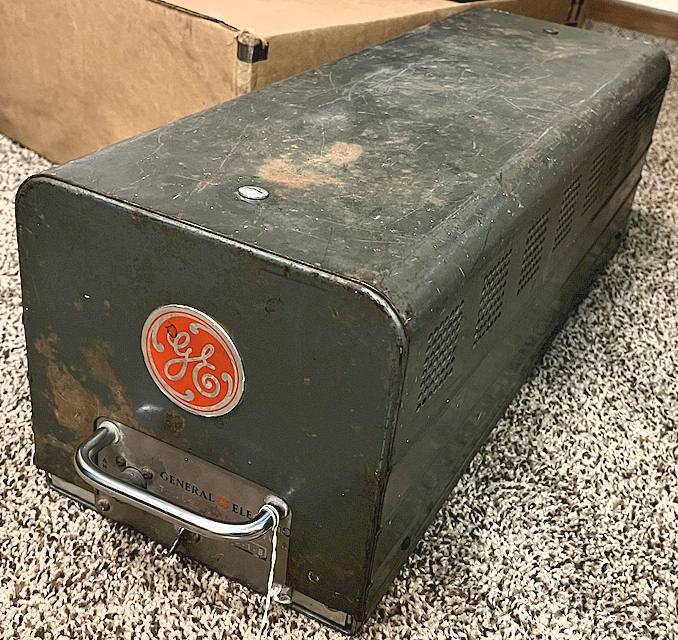
ES-1 (MC-202):
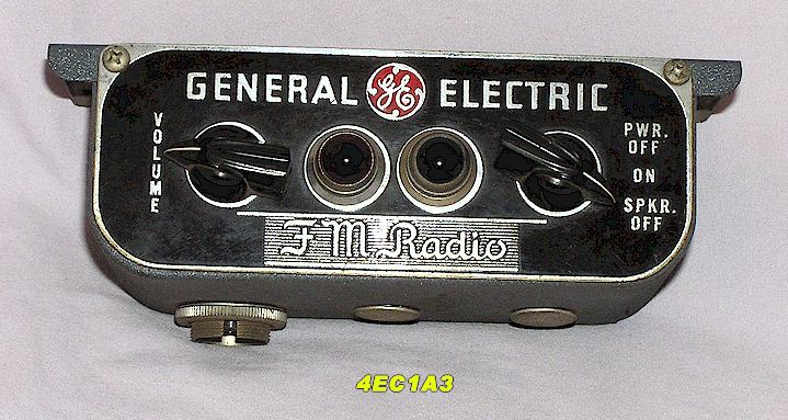
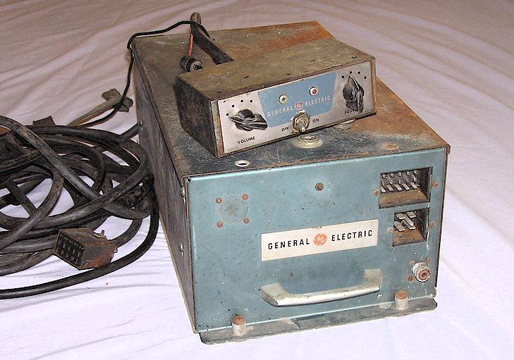
The ES-1 is an interesting set which dates from January, 1947, and was GE's first single unit VHF high band radio. Its long, narrow coffin-like chassis is constructed in platters which fit onto a chassis tray arrangement. It was also sold as a mobile telephone, where they were used with an external decoder and a Western Electric Model 41A control head. There were also "common carrier" mobile telephone versions of the ES-1 which used a conventional GE control head, as shown below, and with a separate handset cradle. This series was only manufactured in a VHF high band version, and was probably intended to capitalize on the1946 FCC decision to open up VHF high band to land mobile licensees, as of October, as well as require that any new police systems be licensed for that band absent a showing of need for a low band system. The ES-1 is usually found as the ES-1B, but presumably there was an ES-1A as well. the ES-1-B went at least to the B5 series.
The 4EC1 control head below was supplied with the ES-1 sets:
ES-12 (MC-203), MC-204, MC-205:
The ES-12 is another high band Pre-Progress 10 Watt one piece set, completely different from the ES-1B and probably younger by one or two years. There are photos of them in use dating from 1948, so I assume these sets were being shipped by early that year. Information indicates that this set was specifically marketed to the taxicab industry although they were also sold elsewhere. For some reason one of the informal GE history summaries states this set was introduced in April, 1950, yet I am in possession of photographs from 1948 showing it in use.
From a marketing standpoint, the MC-203 seems to have been intended to compete with Motorola's FMTRU-5V "Dispatcher" mobile, also introduced in 1947. Unlike the ES-1B, they are not quite modular and consist of a one-piece transmitter and power supply attached to a separate receiver chassis. Transmitter RF power is approximately 10-15 Watts using a 2E26 as the output tube. These sets saw widespread use as taxi radios and GE was heavily involved in promoting the newly created taxi radio service after 1946. These were also marketed as the foundation for Bell System mobile telephones, hence the blocked-off circular hole on the front panel at the upper left, where a connector would have been installed for cabling to a Western Electric electro-mechanical rotary decoder.
The paint scheme is the same frosted green as the two-piece Pre-Progress Line series and these sets are also referred to as a Pre-Progress mobiles. They also use the same control head as the two piece MC-1 sets shown above. A rather shabby example is shown below. The blocked-off round hole on the front panel was used for an optional Secode style stepper-decoder for selective calling, as in early "RCC" and mobile telephone systems.
Also manufactured by mid 1950 were one piece high band sets MC-205 (25 Watts,) and MC-204 (50 Watts) along with MC-203LP (low power industrial, 3 Watts.)
MC-204, MC-205 and Related Equipment:
Also manufactured by mid 1950 were one piece high band sets MC-205 (25 Watts,) and MC-204 (50 Watts) along with MC-203LP (low power industrial, 3 Watts.) The higher powered sets featured a dynamotor for the transmitter in addition to the vibrator section. A typical example is shown below.
Thanks to Ken Decker WA6OSB
for these photos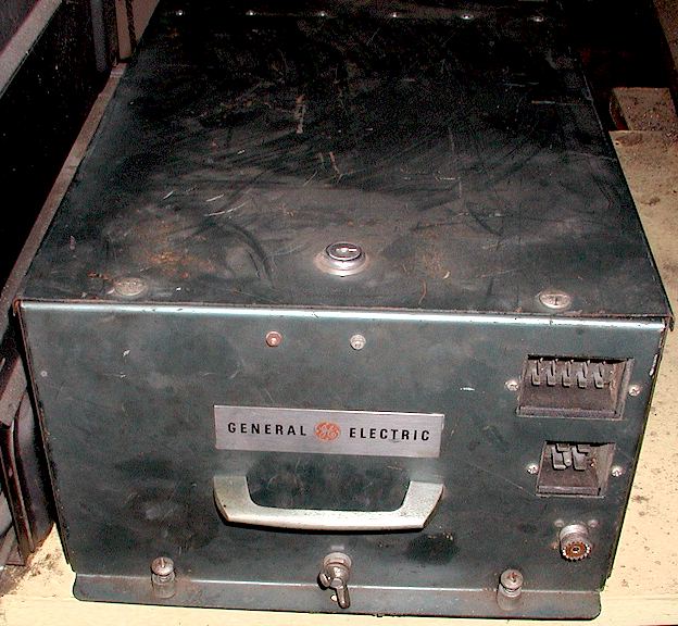
6/12 Volt Conversion Kits:
The first American cars with a 12 Volt electrical system began to appear in 1953 with some Buick models. The majority of American cars were not produced with a 12 Volt electrical system until 1956, after which 12 Volts became the standard. GE introduced a 12 Volt conversion kit in August, 1953 for most of the Pre-Progress equipment still being supported or currently sold, such as the above.
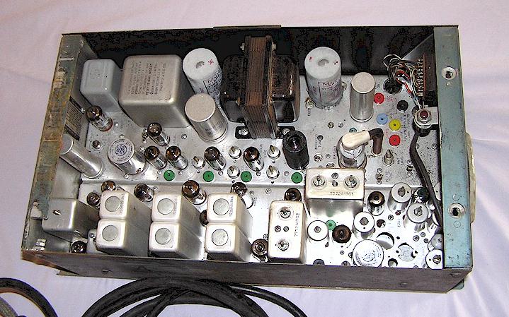
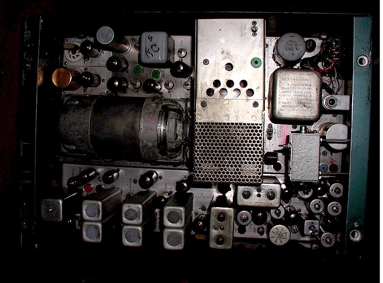
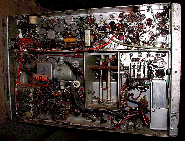
PRE-PROGRESS UHF EQUIPMENT (July, 1954 - 1960)
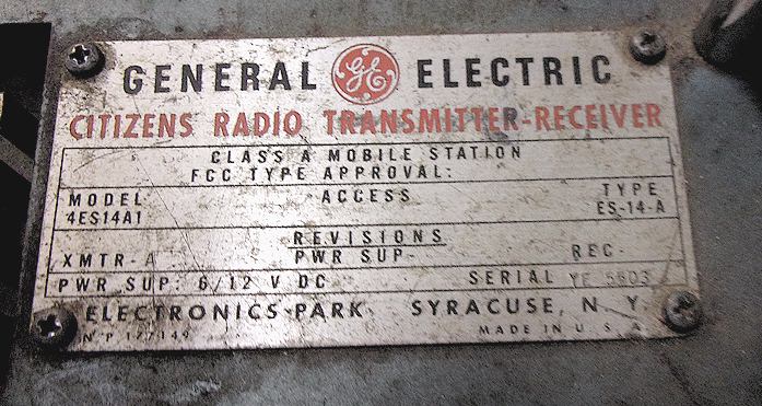
In early 1954, the UHF range of 450-470 MHz was opened to the land mobile industry. GE's entry into this market in July, 1954 was the frosted green colored MC 306 / 316 series UHF FM radio, a large one-piece mobile, vibrator powered, also numbered 4ES14A1 or just ES-14-A.
Many of these first UHF radios were marked and marketed as "Class A Citizen's Band" equipment, referring to the Citizen's Band class of operation at 460 MHz, which was completely different from the well known 27 MHz AM Class D allocation which came a number of years later in 1958.
The MC 306 was an interesting design in that it utilized the control head and accessory group which would not be seen on any other GE models until the introduction of the Progress Line in 1955. The MC306 was intended to compete with Motorola's famous "T44" UHF Research Line equipment. The MC306 used a pair of 2C39 lighthouse tubes in the transmitter to produce approximately 10 watts output. This Pre-Progress transmitter would come to be considered as a success, however the companion receiver was eventually regarded as somewhat of a design disaster. The receiver was subject to excessive drift, and there were various AFC circuits and other attempts to correct this, which were never entirely successful. Motorola's problem was just the opposite; their transmitter was considered a flawed design in that the cavity tuning occurred through the removable top covers, instead of through the sides, as on the GE. The Motorola receiver designs were all considered successful.
Nonetheless, the MC306 saw considerable production and many were later used as mobile telephones on the new Bell and Radio Common Carrier channels in the 450 MHz range. The mobile cabinet of the MC306 would also appear nearly identical to that used on the later Progress Line equipment, although it is not quite the same. Users of UHF in the 1950's were very much pioneers, and with that came the problems expected with brand new technology. It is amazing that GE sold as many Pre-Progress UHF radios as they did.
The MC306 continued in production until approximately 1957, by which time the component density had been shrunk enough to allow incorporation of the basic design into a Progress Line housing and setup. The transmitter was largely redesigned and the use of Lighthouse tubes discontinued for the Progress version. The Progress Line UHF equipment was successful and very popular even though it was only produced for a few years. The Progress UHF equipment was introduced at a national sales meeting in Miami Beach in June, 1956. There is anecdotal evidence that the Pre-Progress UHF equipment may have been still sold up to 1960.
Front panel of the mobile drawer assembly below. Note that this example has been "ham modified" with a non-original antenna connector and a non-original cable in the center of the two connectors.
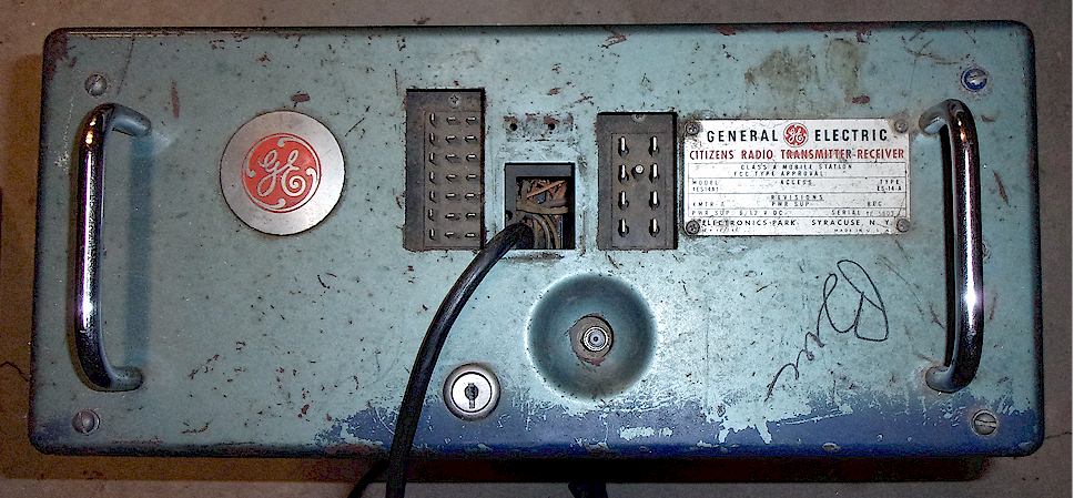
Note that in the interior view below, the chassis has been "ham converted" to an AC power supply in the center along with lesser receiver modifications.
[Needed - better photos of the UHF Pre-Progress radio drawer!]
CLICK HERE FOR AN INDEX OF PRE-PROGRESS MODEL NUMBERS (600kb pdf)
PROGRESS LINE EQUIPMENT (1956-1965)
A major line of demarcation occurs in GE mobile radio history starting with the introduction of the "Progress Line." The Progress Line was one of GE's most successful products and it enjoyed a long production run, from approximately early 1955 to August, 1964. It is probably the most well known of GE mobile radio lines of the vacuum tube era. Unlike its predecessor, the Progress Line mobile equipment was all housed in a single, unitized chassis, containing three independent chassis on a common "basket" framework, namely the receiver, transmitter, and power supply. Base stations used the same chassis "strips" as the mobiles did. All Progress Line mobile receivers and transmitters are tube type with no transistors, although there was a solid state power supply offered for all Progress mobile radios by 1958. After 1958, vibrator and dynamotor power supplies were still available in lieu of the transistorized power supply, presumably at lesser cost.
The Progress Line was available in all mobile radio bands, initially only in the low and high VHF ranges only. UHF, as mentioned above, was not added until 1960. The Progress Line saw extensive sales throughout the world, and is one of GE's most well known mobile radio products. The red knobs on its control heads and their unique shape made them easy to recognize. Together with the older Link Radio products, Cuba's police and military relied on the remaining Progress Line equipment left behind by the Batista government after the fall to the Communists, obviously without any support from GE!
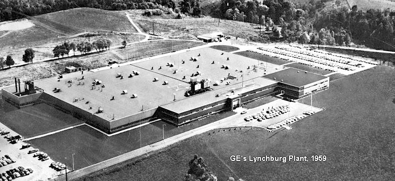
In December, 1958, GE production moved from Utica, New York to the building originally built for the GE Rectifier division in 1956, in Lynchburg, Virginia. Equipment produced in Utica was painted in the frosted light green color scheme of the Pre-Progress era, while Lynchburg equipment was painted a dark blue instead. There were initial production difficulties in Lynchburg due to the humidity in Virginia compared to New York, which mainly centered on difficulties with the plating used on the chassis metals. Utica equipment had been finished with a cadmium plating on chassis sections, however this same process in Lynchburg resulted in black permanent fingerprints and other blemishes showing up on the finished products. As a result, a gold anodizing process referred to by the trade name "Kenvert" was placed on the chassis metals, and cadmium plating was discontinued. With improved air conditioning and production controls, cadmium plating returned on UHF equipment only, for the last six months of Progress production, in 1964.
Progress Line and later equipment assembled at the main GE plant had date coded serial numbers. The first three digits represented the date - - the first digit being the last digit of the year, the second two being the week of production that year, and the balance of the digits being the actual number of radios made at the time of that unit, that week.
There was also an assembly plant in Redwood City, California which assembled chassis into complete radios and performed tuning and final check for customers in the western areas of the country to cut delivery time. Redwood City equipment will have a serial number prefix of RA-. Redwood City serial numbers do not appear to carry date codes.
Progress was manufactured in myriad models, impossible to list here in any comprehensive manner. There were regular mobiles, railroad radios, base stations of all configuration, low powered industrial sets, mobile telephones, and three-wheeled motorcycle sets (for some reason GE did not produce a "solocycle" two-wheeled motorcycle set in the Progress series.)
Progress control heads typically look like the one shown below, although there were multiple frequency and special option heads with more switches and knobs on the front than this one. Progress microphones for the Utica made radios have a green metal housing, as on the Pre-Progress radios, while the microphones for the Lynchburg made radios have a gray plastic Shure dynamic type. There was an abundance of different "special" faceplates and switch locations over the years.
The photo below shows a Redwood City,
California assembled, Lynchburg manufactured, Progress transistor-powered low
band mobile used by the City of Corte Madera, California.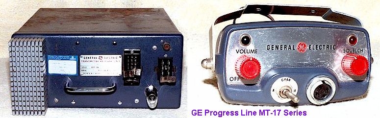
Vibrator powered Progress Equipment is shown below:
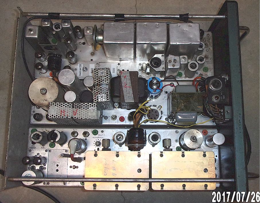
Below: Unusual Utica manufactured Progress Line head apparently made for some large police agency. Note separate transmit and receive channel selection with "Cars-Sta-Both" (dual front end?) and "Sher" switch (second receiver?) Presumably "Sher" meaning "Sheriff." If anyone knows where this was originally used, do let me know! This was obtained from the long-gone Gregory Electronics in Saddle Brook, NJ back in the 1970's.
Update 5/2011: This radio is apparently part of the early Illinois State Police radio system prior to the introduction of the ISPERN radios. The following comment was seen on a radio forum:
State Police low band
radios in the day had a "Sheriff" switch on them that changed the RX
freq on LF1 (42.50) to 39.50 for this method of communications. Sheriff's squads
had similar set ups in reverse to allow them to monitor 42.50 and talk out on
39.50. This way each agency transmitted on channels they were licensed for.
Eventually VHF High band radios became more available, especially after all the
thousands of ISPERN radios provided by the ISP to local and county police
agencies. The Sheriff's Option switch was not included with the later
generations of ISP low band radios although some were programmed with a channel
slot with 39.50 for receive and 42.50 for transmit for those troopers in
districts that still used 39.50.
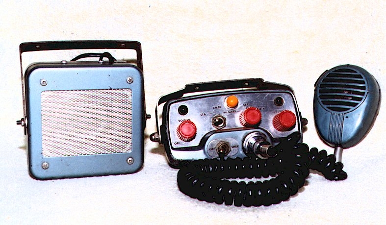
Photo below of New York State Police "Thruway" 1957 Ford. Note pair of Progress Line first generation radios with handsets rather than microphones, one for the "Thruway" system and the other for regular NYSP channels. Thanks to Tom Sheehy for this information.
Progress Line Tabletop "TI" Series base station:
While this page covers mobile equipment only, the photo below shows how GE modified the standard Progress Line mobile configuration to be a tabletop base station. Note the ventilated top cover. Behind the front panel is the regular panel of the wide case Progress Line mobile "drawer." The example below is circa 1962-63. Note that some time after about 1961, the red "Progress" knobs seem to have been replaced with red "TPL" style knobs, except shorter than those used on the TPL models. there was also a "Utility" base station with a smaller head, identical to a front mount Progress Line mobile except for the AC power supply.
Photo courtesy Ben Kittredge WA1PBR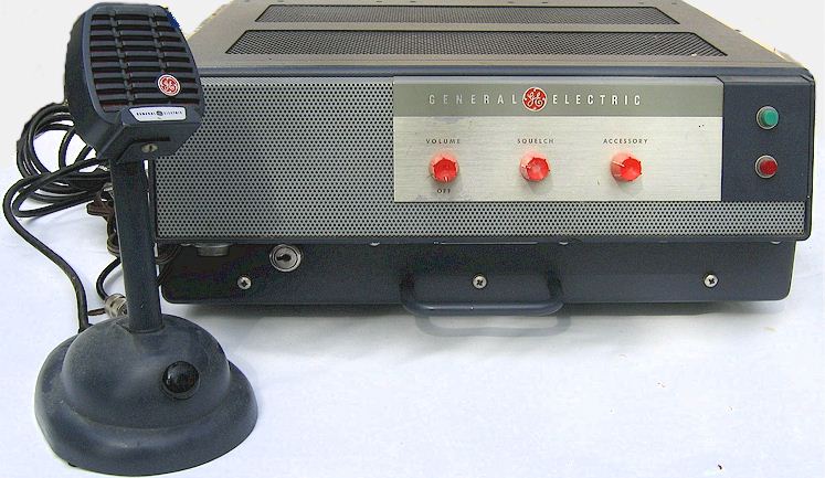
PROGRESS PACK SETS (1958-1962)
Progress Line pack sets were introduced in April, 1958, and used GE's first fully transistorized receiver. This receiver in a modified form would be the basis for the new Transistorized Progress Line described below. They were not common and are rare today. They were made only in VHF low and high bands, and there were two versions of them as well, early and late. The later versions made use of the Transistorized Progress Line receiver chassis almost in its entirety. The transmitters were unique, making use of wire-lead subminiature tubes. The usual power supply was a dry battery box containing "B" and "A" batteries, although late models featured a nickel-cadmium rechargeable battery supply with a DC-DC converter, Typical model numbers were HN-11 and HN-13. The styling of these pack sets was rather attractive and it is not known why more were not sold, nor why the design was not incorporated into a motorcycle radio. Progress pack set production presumably ended by late 1964 with the introduction of the Porta Mobil radio.
Photo courtesy Ben Kittredge
WA1PBR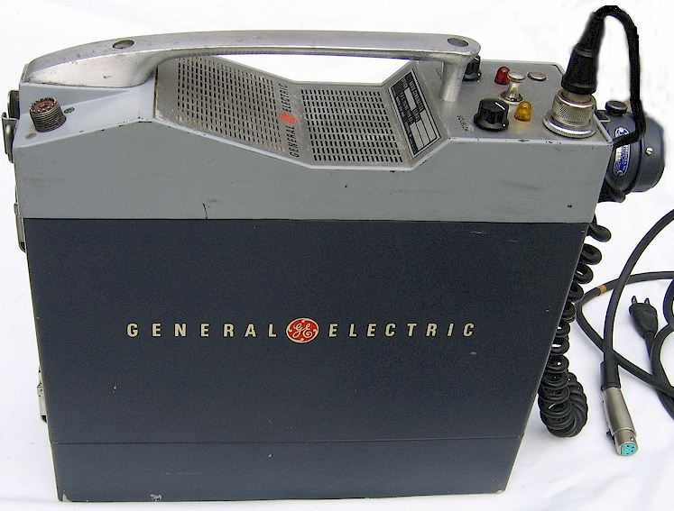
NOTE REGARDING MANUALS: Every month I receive at least several requests for manuals for the equipment listed here. I am not a manual vendor and not a copying service and no longer have easy access to my manual library. I am not retired and run a small business single-handedly. I simply don't have time to scan and clean up or photocopy and mail lengthy manuals, most of which have long fold-out schematics. Therefore, unfortunately I no longer have time to respond to requests for manuals unless you have something on my want list to trade.
Ver. 04/19/2024 © Geoffrey C. Fors 2008 All rights reserved