What's New:
1/23/2014 - Added photos of different Deluxe Line cases 5/17/2014 - Added photo of Deluxe Line dummy heads
7/9/2014- Added photos of FMTRU-40V 7/16/2014 - Added photo of FHTRU callbox to Page Two
9/1/2016 - Added photo of Deluxe base station 9/22/2020 - Added photo of FMTR-80D
MOTOROLA
FM
MOBILE 2-WAY RADIO EQUIPMENT
Part One, 1941-1957
Introduction
Please note that this page is regularly revised and added to. There will be some models not shown and some information missing, which will be added in time. The years given are usually approximate, as exact records are not publicly available if they exist at all.
The Galvin Corporation created what they argued was the first production AM broadcast car radio, in the early 1930's. Up through the mid-1930's, they also made specially modified car radios to receive police broadcasts, on a "to order" basis for nearby police departments. These were the days when the company was small enough that one could walk in off the street and have a special modification of a "stock" radio done almost "while you wait." Galvin began producing "Motorola" brand mobile AM police one-way radio equipment in 1937, on a large scale, with a modified broadcast automobile radio first called the "Police" and later dubbed the "Police Cruiser." In approximately 1939, Galvin introduced two-way operation with the T-69-20A mobile police transmitter, a VHF AM two-piece unit which operated in the 30-40 Megacycle range. Base station transmitters and receivers were also produced to communicate with this mobile equipment. The pre-war Galvin AM equipment is detailed on its own separate page, PREWAR MOTOROLA POLICE RADIO.
NOTE REGARDING MANUALS: Every month I receive at least several requests for manuals for the equipment listed here. I am not a manual vendor and not a copying service and no longer have easy access to my manual library. I am not retired and run a small business single-handedly. I simply don't have time to scan and clean up or photocopy and mail lengthy manuals, most of which have long fold-out schematics. Therefore, unfortunately I will no longer respond to requests for manuals. Possible sources are Vintage Manuals on the web, or eBay.
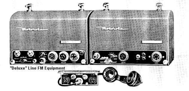
Deluxe Line (1940-1950)
In 1940, the Connecticut State Police adopted a VHF FM two way system in the 39 MHz band, manufactured by Fred M. Link's Link Radio Corporation. The Link contract was the first large scale two way FM VHF system in the country and was so successful that it was held out as a model for other departments to emulate. It should be noted that many articles, and Link's own advertising at the time, give the impression that Link was first with an FM VHF two way radio, but this is not actually the case. GE had purchased a license to pursue FM development from Major Armstrong, inventor of FM, and had produced working VHF FM equipment since approximately 1938, although it was essentially experimental without meaningful sales. This equipment had been examined by Professor Daniel Noble, consultant to the state police, who rented some of it (probably for "reverse engineering!" However, he found it "unsatisfactory" for reasons not fully disclosed. The Fred Link system was built to Noble's specifications, by modifying existing VHF AM equipment (the 8-UA receiver and 15-UBX transmitter.). Noble would shortly thereafter join Galvin Corporation and supervise the production of Galvin's own line of two-way FM radios, which not coincidentally looked very much like original Link equipment, and was in direct competition with it. This first line of Galvin FM equipment was dubbed the Motorola "Deluxe" line, and Galvin at that time ceased design of any new "Police Cruiser" receivers or T-69 series AM transmitting equipment (although production of both continued throughout the remainder of the 1940's.) Fred Link encountered financial difficulties and sold Link Radio in 1950, undoubtedly due to the competitive pressure from much better funded Motorola.
Once Motorola began producing FM equipment, they placed all emphasis on VHF FM and dropped advertising for conventional AM 2-Way products other than an occasional mention in brochures and advertising.
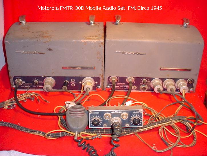
The Deluxe line consists of a two piece radio set, mounted in the trunk of the vehicle. Unlike the Link FM equipment, the Motorola equipment placed the vibrator power supply for the receiver inside the receiver cabinet, rather than in a separate external case. Perhaps by virtue of being approximately a year newer than the Link equipment, the Motorola was more advanced in design (as well as being more complicated.) The Deluxe line was produced from approximately 1941-1950, at which time it was replaced by the "Research" line, Motorola's new flagship two-way radio product.
During its production run, the Deluxe line was produced in many configurations and models, for both low band (40 MHz), mid-band (75 MHz) and (later, after 1946) high band (150 MHz) systems, and was sold throughout the world. The equipment would later be referred to colloquially as "Coffin Units" or "Doghouse Radios" by the two-way radio trade.
The transmitters and receivers were labeled individually with their own model numbers, FMR- for the receivers and FMT- for the transmitters. After the end of the war, a "U" was added denoting high band VHF, for example FMTU-30D.
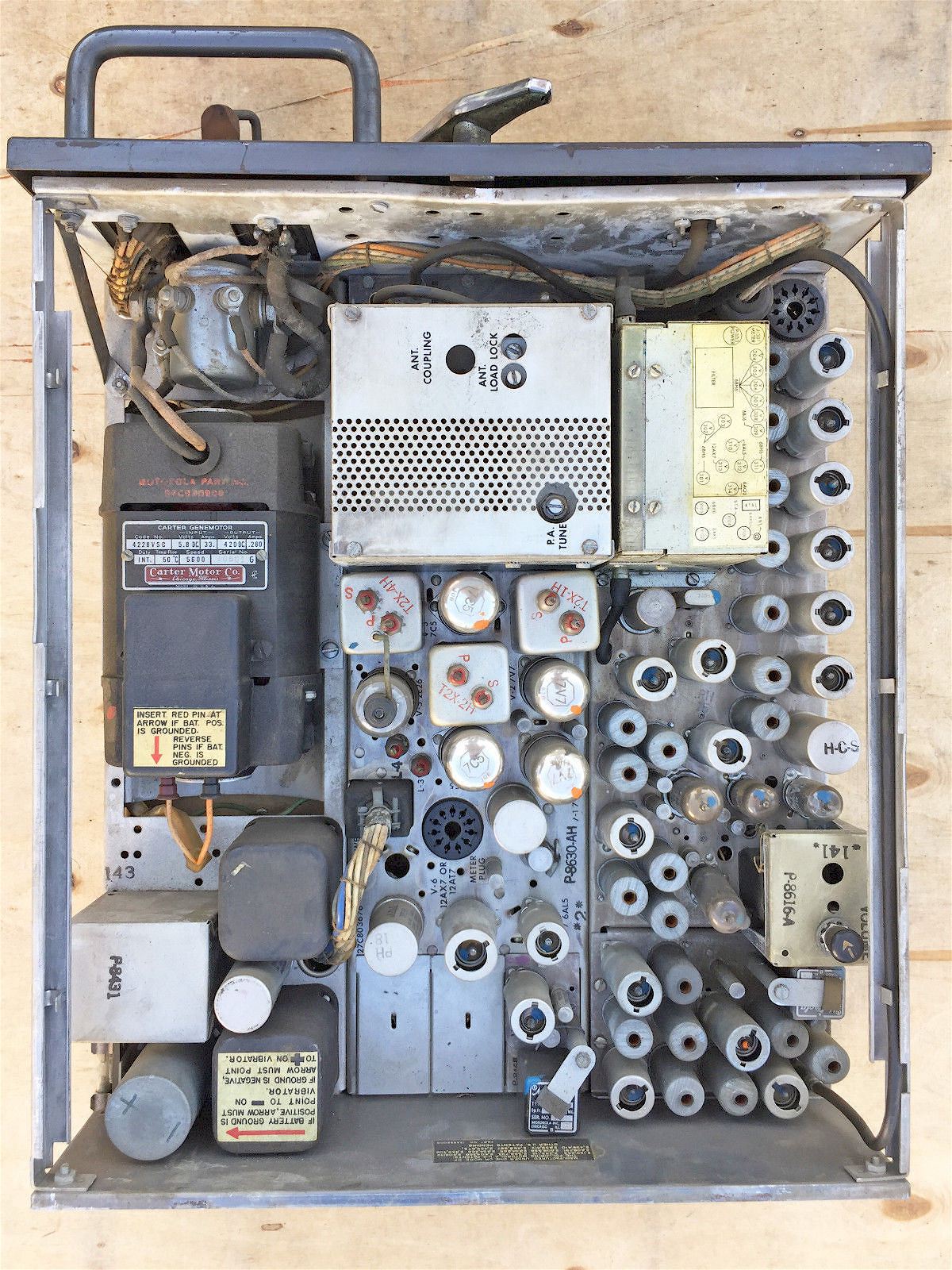
There were various model numbers within this scheme. One major difference is that sometime around 1945, a completely new receiver design was introduced, called the "Precision" Deluxe. These FMAR-13V receivers (typical model number,) used Loktal tubes and were also called the "Precision Selectivity" receivers. The original low band receiver with octal tubes was the FMR-13V. There was also a unique chassis number, usually beginning with P8--- which identified the exact and specific chassis in use. Note that 150 MHz band receivers were not sold until after the 1946 FCC ruling opening that band to licenses.
The transmitters were available in various power levels and power supply types, and included such numbers as FMT-16V for a 20 Watt vibrator powered low band transmitter, to the more common FMT-30D dynamotor powered 30 Watt transmitter. All of the Deluxe Line began as 6 Volt DC powered equipment, although some military applications were supplied with 12 Volt and 24 Volt power supplies. Eventually, some of the equipment was converted to 12 Volts in the field when American automobiles changed to 12 Volt batteries in 1956, although the majority were taken out of service and scrapped at that time. A twin 807 tube "high power" low band Deluxe transmitter (50 Watts) was available by some time in the late 1940's, although the current to run it on a 6 Volt system was extremely high and required a vehicle equipped with a high output generator or a first-generation Leece-Neville alternator.
The individual transmitter and receiver scheme allowed mixing and matching, to some extent. Fir example, a low band receiver could be used with a high band transmitter (rare) or more commonly, only a Motorola receiver or transmitter would be purchased, and the complement would be a Link or RCA or GE unit. For example, California Highway Patrol used the Motorola low band Deluxe transmitters with a Philco AM medium wave receiver, as well as the under-dash Motorola "Police Cruiser" AM sets. Other California departments used a Motorola "Golden Voice" car radio, modified by the Oakland, California Western Auto franchise for police use, and later mated it to just a low band VHF FM transmitter such as the Deluxe series (or a Motorola T-69-20A AM transmitter.) It is believed that this Western Auto franchise also sold modified Wells Gardner car radios under the Western Auto name as police sets.
A complete "Deluxe" model would be numbered, as an example, "FMTR-30D" or "FMTRU-30D," the complete model number apparently taking the transmitter numeric model number rather than that of the receiver. The complete model number only appeared in the manuals and was not stamped on the equipment itself.
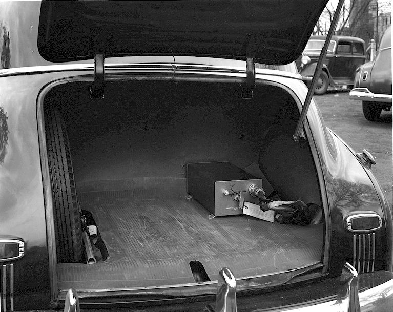
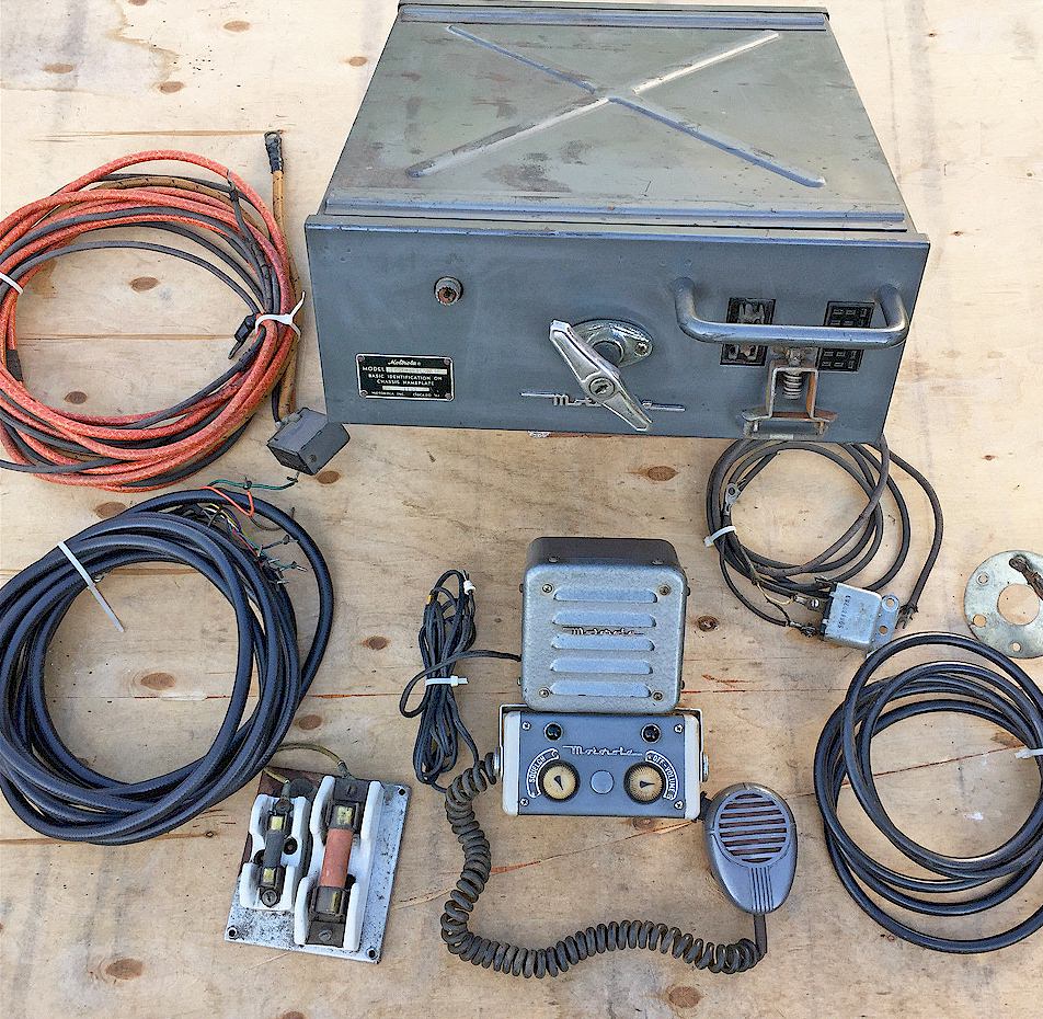
Shown below is the earliest Deluxe line design. Later versions had a pull-handle cover latch instead of the top mounted twist handles. Note that there are a couple of ways to tell a high band from a low band Deluxe set in old photos. The low band sets use prewar "Bendix" style antenna connectors which have a smaller tightening ring and are generally smaller in appearance than the more modern "UHF" Amphenol connectors, which were used on the high band sets. Also, on the high band transmitters, there is a small "coupling" screw adjustment hole located on the panel on the left end just above the antenna connector. The antenna connectors in the photo below with the legend "Mobile Transmitter and Receiver" can be seen to be UHF style, therefore those sets can be identified as VHF high band.
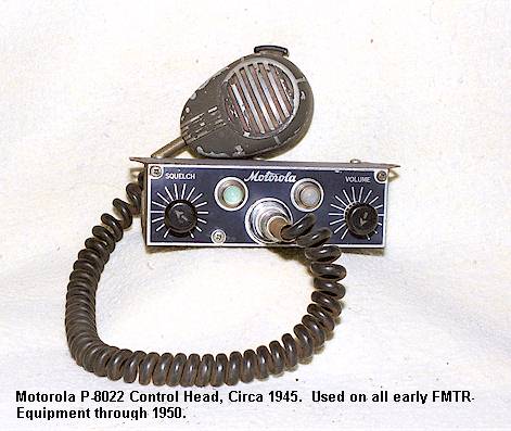
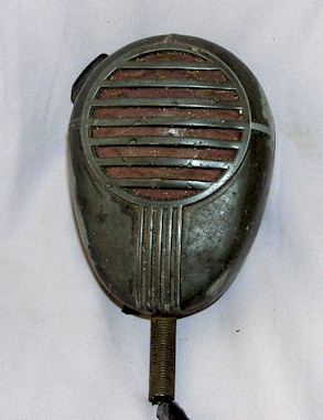
Note that the coiled microphone cord in the example below was a postwar replacement. Coiled cords seem to have not been available until after WWII. The original cords were straight rubber in construction.
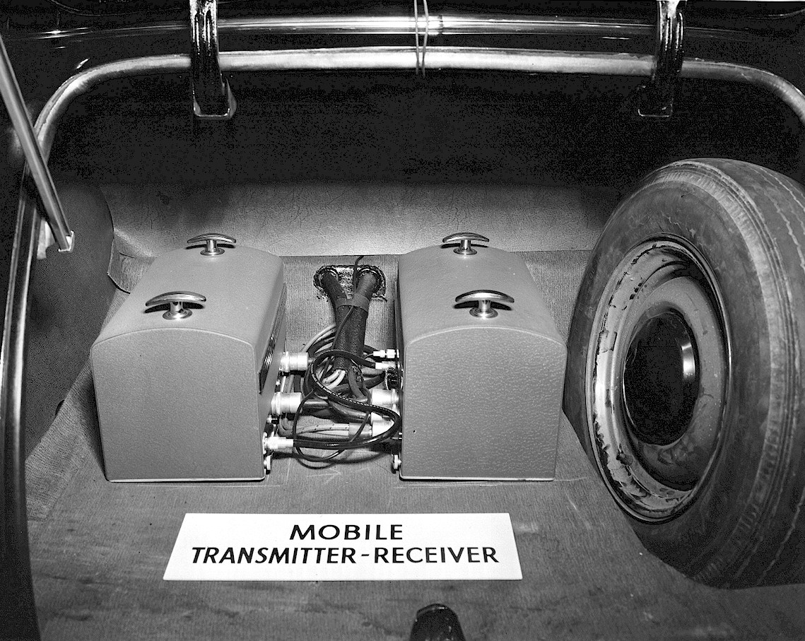
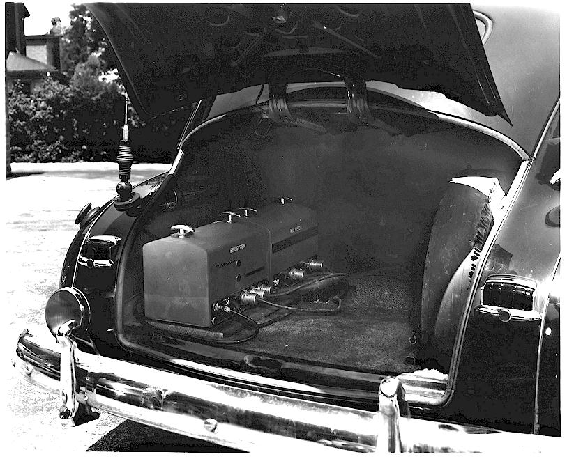
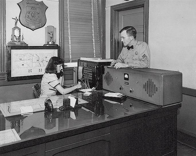
Note the installation below in a police car in the Philadelphia area circa 1948. Not a lot of tread left on that spare! At the time the Bell System was trying to get into the mobile radio business by leasing and maintaining two-way radios. This business plan was short-lived and seems to have taken place only or mostly in the northeast parts of the United States.
Second version cover:
Here is a photo of a second generation cover design for the Deluxe series. Note that the receiver shown has a later and incorrect antenna connector. There was also a third generation cover which deleted the top handles and provided a front pull-handle instead.
Third version cover:
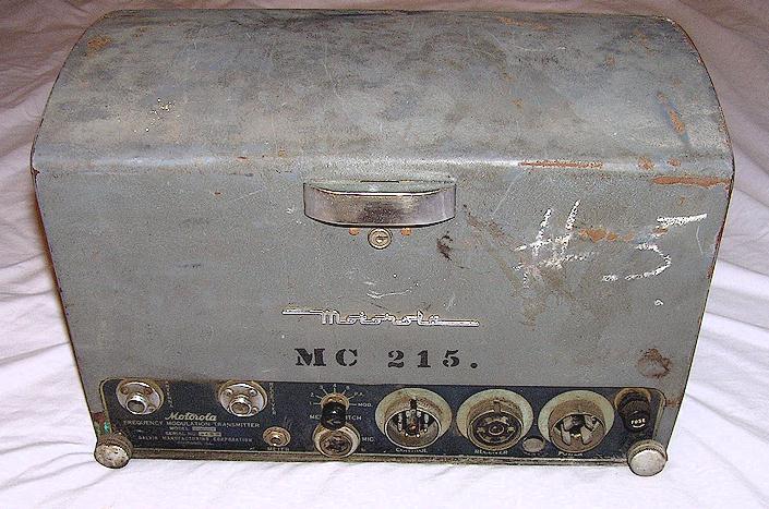
Here is the final cover design. Perhaps car trunks were getting shallower and a pull-handle was easier to deal with. The low band transmitter shown below is an interesting example. FPT-25V is the model number, which translates to a "portable" 25 Watt transmitter. It uses a vibrator power supply rather than the "normal" dynamotor type and runs on 6 Volts DC. Perhaps it was originally intended as some kind of "portable" transmitter mounted on a plywood sheet along with a receiver for field command posts and that sort of thing. A virtually identical transmitter with the model of FMT-25V was also made, the original application being standard, in a vehicle trunk. The vibrator power unit seems to have been an option for those who did not want the current drain and start-up surge of a dynamotor, such as in portable work where the equipment was connected to a 6 volt storage battery. Or, a few customers preferred the vibrator power supply despite the somewhat reduced power output of the transmitter (nominally 15-20 Watts versus the 30 Watts of the FMT-30D transmitters.) This one was used in Hollister, California apparently by the San Benito County Sheriff. The "MC" number on it suggests it originally was used by the Monterey County Sheriff, as that is the Monterey County equipment numbering system of the time. Service and licensing tags inside it indicate that it was in use in 1950.
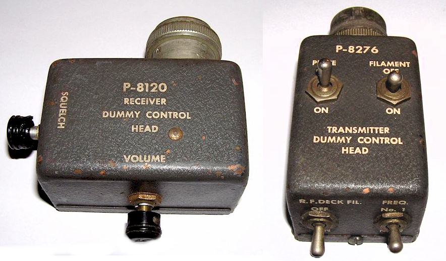
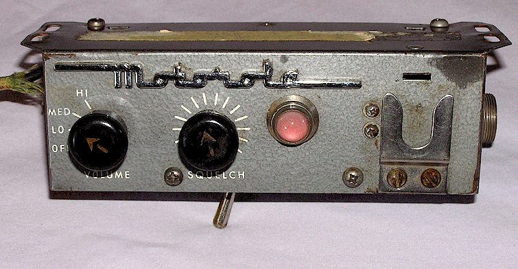
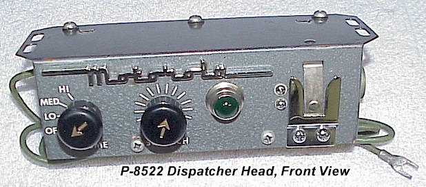
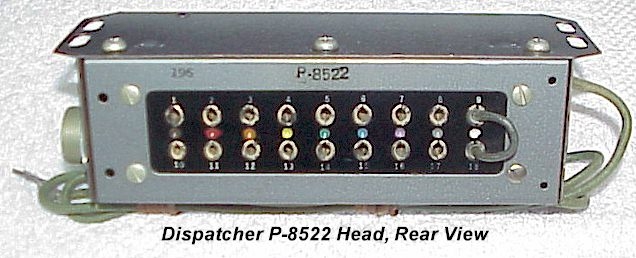
Ever wonder how these were serviced on the bench? Shown below is a set of "dummy heads" which plug into the front of each in place of the control cables and eliminate the need for a complete accessory group on the bench. They also allowed service in the vehicle without having to go around into the car passenger compartment and change things on the control head.
HF Versions: Please note that the Deluxe Line mobiles as shown above were also apparently produced in a high frequency AM version for the U.S. Forest Service. I have no images of them, model numbers or documentation. If you can help with any of this obscure aspect of Motorola history, let me know!
BASE STATIONS:
With AC power supplies, the Deluxe chassis were usually assembled inside a rather large tabletop cabinet as a base station version, as seen below, circa 1948:
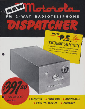
Dispatcher (1947-1952)
The Dispatcher was an "economy" series of two way one-piece radios created in approximately 1947, probably as a response to the FCC's opening the VHF "high band" 150 MHz channels in 1946, requiring that new police licenses be on that band absent a showing of need to still use low band. The Dispatcher was the forerunner of the Research Line, which would eventually replace the Deluxe series in the early 1950's. Unlike the Deluxe equipment, the Dispatchers were built using miniature tubes on two small channel-shaped chassis (called "strips" in the industry) and unitized into a single slide-in cabinet with an optional key-lock (called the "drawer" in the industry.) Dispatchers offered only a low power transmitter, in the 10 Watt range, and were available in either low or high band VHF. The Dispatchers were typically numbered FMTR-5(V) (low band) or FMTRU-5(V) (high band), and were known as the "5V" in the industry. Because of the small size of the strips in the Dispatchers, they were also mounted in black steel Harley Davidson "tubs" and placed in the saddlebag area of police motorcycles. The cables and control head for the Dispatchers do not interchange with the Deluxe line. The Dispatcher used a circular connector of the Cannon AN- series (later re-designated MS-) and the new Amphenol "UHF" connector for the antenna socket. Unlike the Deluxe Line, the Dispatcher control head could offer a micro switch under the microphone hang-up clip which would shut off the transmitter tube filaments when the microphone was hung up after use. The microphone hangs on the front of the control head itself in Dispatcher installations.
The Dispatcher "drawer" consists of only two chassis; the receiver chassis and the combined 10 Watt transmitter/power supply chassis which used 2E26 tubes in the transmitter power amplifier. The receiver used all miniature tubes and offered somewhat less sensitivity than the Deluxe line, and used a "derived" IF section which was not crystal controlled. The receiver had rather poor selectivity. The Dispatcher transmitter used a 2E26 output tube and the power supply consisted of a synchronous vibrator for the receiver and a non-synchronous vibrator for the transmitter, rectified by a 6X5 octal based rectifier. The Dispatcher transmitter was of course wideband FM, and like the Deluxe line, there was no deviation control offered.
It appears that there was no specific speaker supplied with the Dispatcher series; initial models seemed to have been supplied with the square louvered speakers later used on the Research Line radios of the 1950's. Some sets were ordered without speakers, as it was popular at the time to make use of a broadcast radio speaker mounted behind the grille of the car's dashboard at its intended place. Few fleet automobiles were purchased with radios (or even heaters!) so the space was available and represented a cheaper and better alternative to the purchase of a stock Motorola speaker.
The Dispatcher was widely used in taxi fleets and small police departments, but was produced only for a few years, approximately 1947-52. The low transmitter power and rather dismal receiver sensitivity on VHF high band limited the Dispatcher to small geographical areas. Most Dispatchers seem to have been made for the VHF high band range. Additionally, new FCC restrictions on stability and narrower channel spacing were on the horizon, and Motorola chose to discontinue the Dispatcher and bring out a totally new model rather than attempt to upgrade the original design.
The model name "Dispatcher" would continue to be used over and over again in succeeding years on newer models, for example the "Transistorized Dispatcher," the "Industrial Dispatcher," the "Airport Terminal Dispatcher" and the "Solid State Dispatcher."
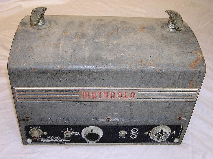
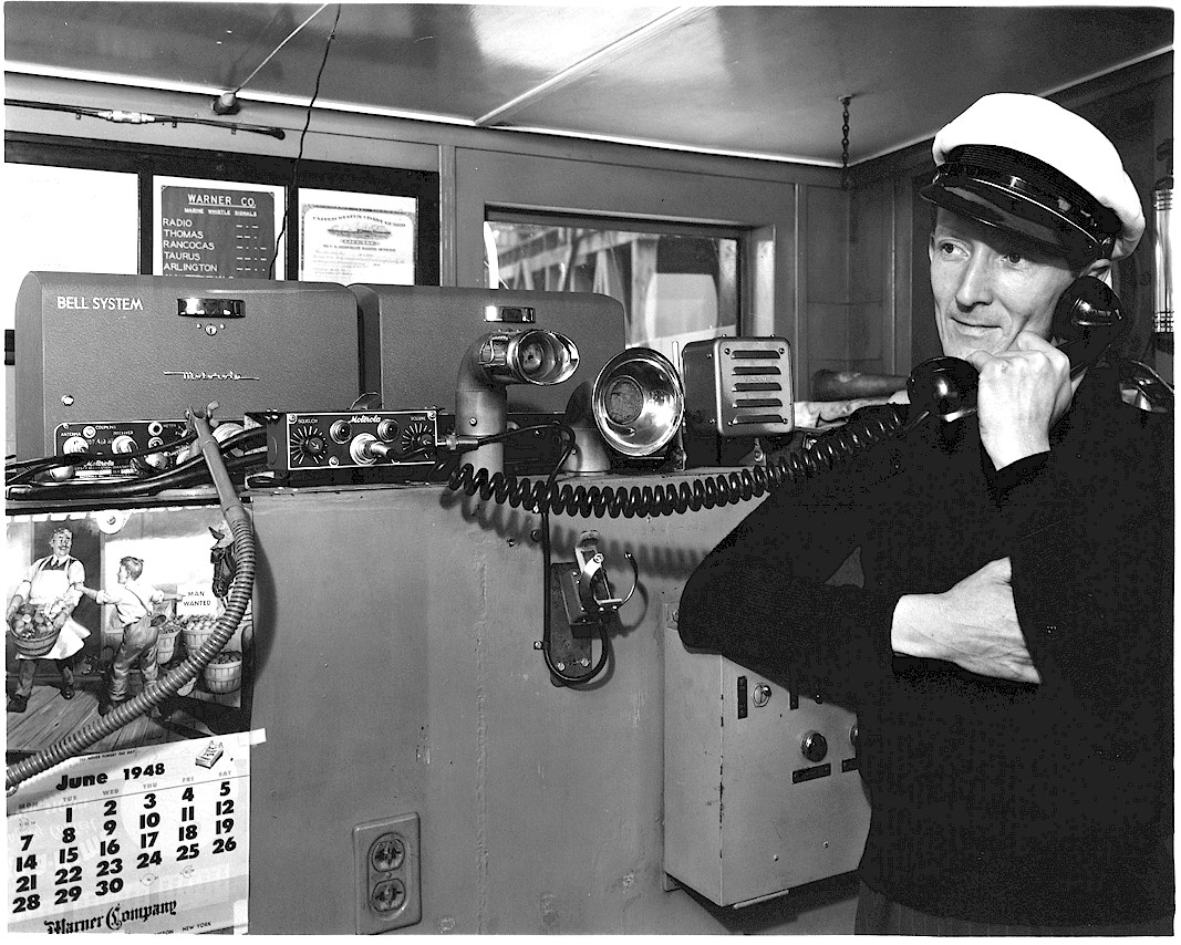
The 1948 photo below shows an FMTRU-5V mobile leased to a police department
by the Bell System. In the northeastern states, such as Pennsylvania and
Delaware, the Bell System was
heavily involved in leasing two way radios and mobile telephones to police and
fire departments. Apparently the Bell System felt that handsets were
better than microphones, and the majority of installations featured a handset,
such as in the photo below. This made for somewhat of an odd appearance,
since the 5V head is unique in having a microphone hanger on the front panel.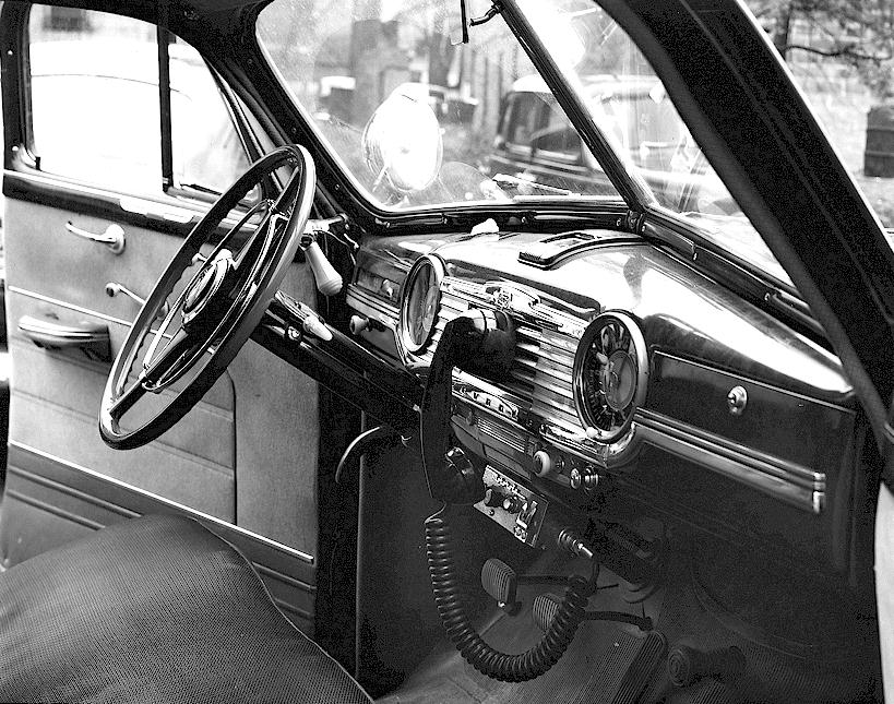
This variation head, new old stock seen in Spring, 2012 on eBay, has a green pilot lamp.
Research Line (1949-1953)
The Research Line was introduced in 1949 to replace the aging Deluxe equipment and was the basis for one of the most successful and reliable two-way radios in history, as well as one of the most prolific. The Research Line was an extension of the concepts introduced with the Dispatcher sets, namely one-piece radio "drawers" using individual strip-chassis, with all-miniature tubes in the receivers. Unlike the "5V" Dispatchers, the Research Line was available in many configurations and with many different receiver or transmitter chassis combinations.
RECEIVERS:
The receivers offered in the Research Line included "Unichannel" and "Sensicon" types. The Unichannel receiver was a narrower chassis version, less expensive, but with nearly the same performance specifications as the Sensicon. The Sensicon receiver was the most expensive version, was on a wider chassis than the Unichannel, and offered more options such as multiple channels and a carrier operated relay. In the VHF high band version, the Sensicon receiver had tunable cavity "pipes" in the front end (Sensicon "A".). Both types of receivers featured Motorola's new "Permakay" IF filter, for "Precision Selectivity," although they could be ordered without it (few were.)
TRANSMITTERS:
The transmitters were available in power levels from 10 to 60 Watts, the higher powered transmitters having a wider chassis and using an 829B or two 2E26's as the final amplifier/s, and were referred to as the "A" series transmitters.
Depending upon the chassis selection, the Research Line sets could be purchased in a 10" wide cabinet or a 15" wide cabinet (or specially ordered in an even wider, 17" case !). All Research Line mobiles used the same control head, although that control head was available in many different configurations. The Research control heads are recognized by their white ribbed knobs with black pointers and the "squelch" and "volume" nameplates being riveted to the panel plate. Research was produced from approximately 1951-late 1955. Research also was the first series to offer a 450 MHz UHF radio, near the end of Research model production in approximately 1955, the T44-1.
POWER SUPPLIES:
The power supplies were available in vibrator, dynamotor and AC Utility (desktop base station.) The dynamotor power supply was used on the highest power models, as apparently the vibrator design was not up to the task at the time. The lower power models ( FMTRU-41V, FMTRU-40V for example, were all vibrator powered.)
Example below is a low band FMTR-80D single channel mobile. See model list below.
Research Line heads:
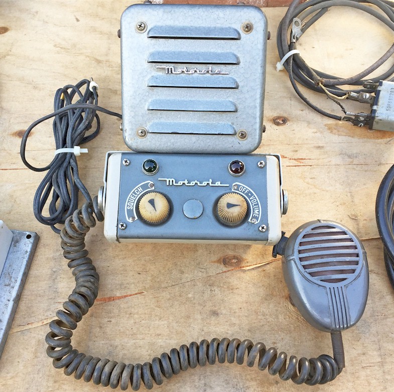
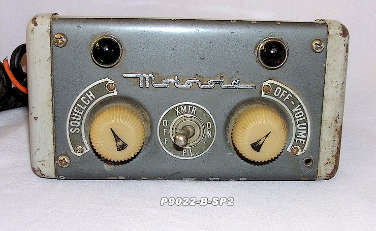
Typical Research heads appeared as the one above, and were usually found with the louvered speaker and mike shown. Handset models were also available, as were heads with special small multi-frequency and multi-tone knobs in the center area (by special order.) The head shown below was a somewhat special model with a switch to turn off transmitter filaments to save battery power in a 6 Volt vehicle, and was used with a 15" width high-power Research mobile. 12 Volt models drew less current and did not have the standby switch as an option.
The microphones were a standard Shure carbon mobile microphone of the CB-12 variety. A rather shabby example is shown below.
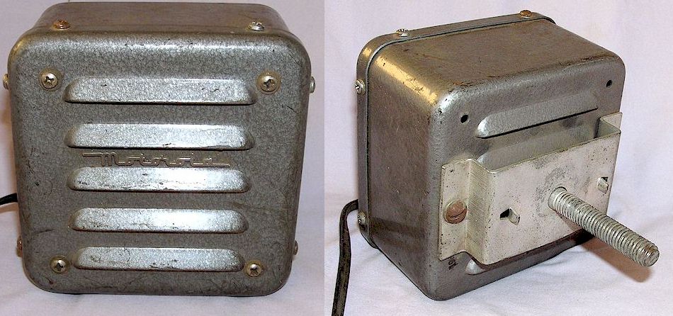
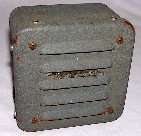
The typical speaker was as shown below, although this speaker was also supplied in a gray wrinkle finish. The mounting intent was that a single hole would be bored into the vehicle firewall, the threaded rod placed through it, and a nut in the engine compartment securing the speaker. Research was the last series to use this curious speaker mounting, an apparent throwback to 1930's auto radio mounting schemes, since even the Deluxe series used a modern "trunnion" dash or firewall mounted "U" bracket.
Also curious is that none of the paint color schemes of the speakers match the control head or microphone paints! Some early examples of this speaker were supplied with a gold water-slide decal with the Motorola logo rather than the chrome-plated script shown here.
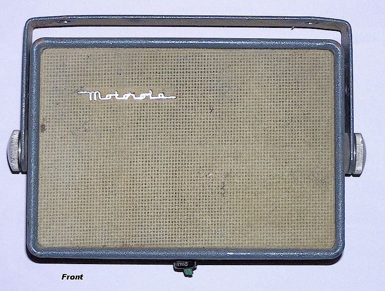
THE STRANGE TU 215 MYSTERY SPEAKER:
This is a speaker you won't see pictured in the service manuals, but they do exist! The TU 215 speaker makes use of the "inside out" voice coil and magnet assembly used on Motorola TV sets of the late 1940's or early 1950's. This style speaker has the voice coil and magnet on the front side of the cone instead of behind it, making for a very compact speaker. For some reason Motorola decided to discontinue production of this style TV speaker, and sent the excess inventory to the Communications Division where they were made into mobile radio speakers with open, flocked grilles on front and rear. These were shipped during the approximate period of 1953-1955 and all of them seem to be undated. I had never seen one until quite recently, when two of them came my way. They are not as robust as the speaker above, and may have had a short lifespan.
Typical Models:
It is almost impossible to list all the model combinations which were made in the Research Line. The most common ones were the "41V", the "80D", and the "140D" series.
41V: The FMTR-41(V) and the FMTRU-41(V) were the smallest and possibly the most popular sets of the Research Line. They were in a 10" wide case and featured the Unichannel receiver with a 10-15 Watt level transmitter, with a third chassis containing the separate power supply. The 41V used a vibrator power supply with a selenium rectifier, and was available in one or two channel models. Unlike its predecessors, the 41V has an adjustable deviation control on the transmitter. The 41V was available in either 6 or 12 volt versions, but not both in the same chassis. Unlike any other equipment either prior to it or contemporary with it, the 41V was available in either a dash mount or a trunk mount configuration, as well as a desktop base station. [Photo pending]
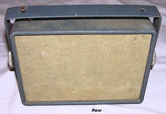
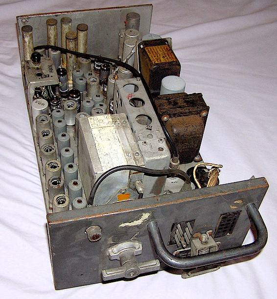
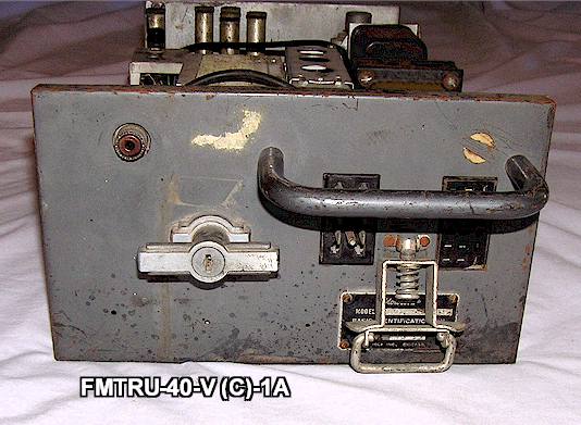
40V: The FMTRU-40V is an interesting set which appears to have been made from production scraps and primarily for the VHF high band taxicab market . It uses the same control head and accessories as the other Research Line radios. It seems to have been intended as an improved version of the older Dispatcher "5V" series and probably was one of the least expensive models. It consisted of a wide chassis high band Sensicon "A" receiver, mated to a Dispatcher transmitter/power supply combination, in a 10" wide cabinet. This is unusual in that the Dispatcher equipment was already discontinued at the time the 40V was being sold. Evidently Motorola had a surplus of Dispatcher transmitter/power supply combinations left over. The choice of a Sensicon A receiver rather than a Unichannel receiver is also interesting- - evidently the set was designed to be used in urban areas with a high concentration of interfering signals and intermodulation distortion, which only the Sensicon A receiver with its cavity-pipe front end could deal with. Otherwise, had a Unichannel receiver been used, the set could have been significantly narrower and compact. Most of the FMTRU-40V sets in the west seem to have been sold in the San Francisco, California area to taxicab operators. The example below carries a summer, 1950 production date. The 40V was short-lived because the transmitter failed to meet FCC requirements for stability and control of FM modulation deviation at 15 kHz or less. They are rarely seen today.
80D and 140D: These were the industry standards in the 1950's and made in the greatest quantity.. The FMTR- or FMTRU-80(D) and FMTR- or FMTRU-140D are 15" wide cased mobiles which usually used Sensicon receivers with high power transmitters. In some instances, a less expensive "Unichannel" receiver was used. The 80D used a pair of 2E26's while the 140D used a single 829B in the transmitter power amplifier. The 80D was nominally a 30 Watt transmitter while the 140D was nominally a 60 Watt transmitter. The power supply used a vibrator for the receiver and a dynamotor for the transmitter. The Research Line enjoyed widespread popularity and such a long service life that most of them were converted to 12 volts after the auto industry switched battery voltage standards in 1956, and many were also converted to comply with "narrow band" FM requirements mandated by the FCC in the early 1960's. In the mid-1960's, Motorola even offered a field modification kit which replaced the vibrator/dynamotor power supply in the 80 and 140 series with a 12 Volt transistorized power supply, which included a heat sink which bolted to the front panel and instructions to overstrike the model number on the ID plate with a number punch to read FMTR-140(T) or FMTR-80(T) as appropriate. The chassis used in these mobiles were also used in all manner of upright cabinet base stations, desktop base stations, repeaters and so forth.
Example of FMTR-80D mobile with accessories is shown above, 140D looked the same.
AC Utility: The AC utility was a desktop base station configuration made from an FMTR-41V series mobile configuration, using a built-in speaker and control panel along with an AC power supply in place of the mobile power supply. Full sized tabletop base stations were also marketed, although it was probably more common to see base stations built into 6-foot racks with separate remote controls.
AM Options: Many large police departments still used "medium wave" AM for their station to car dispatch frequency into the late 1950's (Los Angeles even into 1965!), but the old medium wave separate Police Cruiser receivers were no longer produced after about 1949. To address this market, Motorola offered a medium frequency AM receiver strip which could be used inside a Research Line case instead of a Unichannel FM VHF receiver, either with a companion VHF FM transmitter or by itself as a one-way setup. That AM receiver was the P-9075, which was also available in a motorcycle version in a Harley Davidson steel saddlebag box.. A typical configuration might have been an FMTR-5(V) style motorcycle radio, with this AM receiver instead of the usual VHF FM receiver. The model numbers of such sets are not known to the author, but may have been something similar to "FMTR(A)-5(V) or perhaps "FMT(A)R-5(V) SP-xxx." This receiver chassis was built at least through the end of 1955 and probably was carried mainly to accommodate the Los Angeles Police Department, which did not abandon AM on medium wave frequencies until 1965!
Research model numbering change: In approximately 1954, the model numbering scheme was changed from the FMTRU- type numbers to ones usually beginning in "T43G-1, T44A-6 or T51-1", although the equipment otherwise appeared identical. At the time of this change, the T44-1 UHF mobile was introduced, which was in a 15 inch housing and continued with few changes into the new "Twin-V" series after 1956, other than being re-badged "Twin-V" with a model number change to "T44AAV." A number of new models were introduced with various power levels and other options, these being referred to here as the "Second Generation" Research Line, as follows:
Second Generation Research Line (1953-1955)
The Research Line rather quickly evolved from the initial offerings of the "80D" and "140D" sets to a wide variety of configurations in 1953, in addition, Motorola changed the model numbering scheme, abandoning the FMTR- style system to one of a series of numbers such as T51-1 or T43-1, being further expanded to such numbers as T51G-1. In 1954, a UHF radio, the T44A-6 was also developed. Differing series of chassis became available, now the "A" or "G" line series. The "A" series chassis were essentially the same as in the FMTRU-80D or -140D equipment, including the famous "Sensicon A" receiver. The "41V" series mobile chassis strips were discontinued at this time and the "41V" was replaced by the T41G or T43G series radios, using the same housing but featuring the new "Unichannel" style "G" chassis for both transmitter and receiver. The wider cased higher power radios were also available with the "G" series "Unichannel" chassis inside, in which case blank metal filler chassis strips were added to fill the space in. The array of available configurations in the second generation "Research Line" was large. As mentioned, most of the Research Line mobiles were capable of either 6 or 12 Volt operation by the selection of appropriate cables and jumpers on the chassis, but apparently for marketing reasons, Motorola chose to rename the standard mobile radio line the "Twin-V" in approximately late 1955, even though it was largely unchanged from the second generation Research equipment. Late Research radios used the same control heads as the Twin-V equipment, except with glass lenses for the pilot lamps rather than opaque plastic ones.
Ver. 12/12/2020 Copyright Geoffrey C. Fors, all rights reserved