MOTOROLA
EARLY LAND MOBILE RADIO EQUIPMENT INDEX, 1938-1946
This page is an index to the earliest Motorola police radio equipment. It is not intended as an all-inclusive history of early land mobile radio nor of the Motorola Corporation itself.
The Galvin Manufacturing Corporation began producing "Motorola" mobile police receivers in late summer 1936, considerably later than some other manufacturers such as American Bosch, RCA, Link and Philco. At the time, police dispatching was almost exclusively in the 1550-1750 Kilocycle and 2300-2490 Kilocycle ranges, and was of course AM. Prior to this time, Motorola had produced small quantities of mobile police receivers by modifying standard automobile broadcast radios, almost on a "request" basis for nearby police departments. At that time, the company was not so large that personal service was not available to customers on practically a "walk-in" basis!
Motorola eventually settled on the name "Police Cruiser" for their first police receivers, all but the first of which were model prefixed "P69", the initial drawing board offering possibly being called only "Police," but apparently quickly changed to "Police Cruiser." Some prototypes are believed to exist from early 1936 which are not identified on this list. Also, special production equipment, which carried an "SP-" suffix, is not listed here. AM medium wave receivers were still being produced into the mid-1950's, even though the FCC began granting VHF 30-39 MHz licenses for 2-way systems in 1936 and granted permanent VHF licenses on both low and high VHF bands in late 1945. After World War Two, most manufacturers abandoned AM equipment other than as replacement parts for existing systems. No new Police Cruiser models were introduced after the War, although at least the P69-18 was available from existing stock through about 1951. The FCC issued an order after WWII directing that all new license applications for land mobile radio services were to be issued 150 MHz allocations, absent a compelling reason requiring low band or medium wave frequencies.
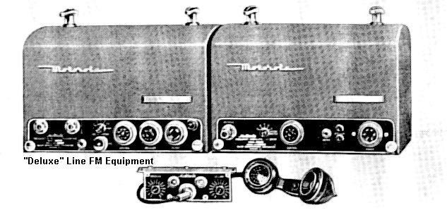
In late 1940, Motorola began selling the "Deluxe" line of equipment, a large rounded-top two piece radio set often referred to as "coffin units," "doghouse sets," or "double humpers." Although primarily an FM product, the Deluxe line apparently was offered in a VHF AM version with a type number AMR-13(V) for the receiver and presumably AMT-30(D) for the transmitter, but this author has never run across any nor found production documentation supporting a "Deluxe" AM transmitter. Information is solicited! In approximately 1948, the Galvin Company officially adopted the name "Motorola, Inc."
In January 1951, as a replacement for the discontinued Police Cruiser series, a Unichannel AM medium wave receiver strip was made available for the new "Research Line" one-piece radio equipment. It was available as either a stand-alone receiver (mounted in a "41V" style case or in a motorcycle side-carrier) or combined with an FM Unichannel transmitter strip in a 10 or 15" mobile case, for those systems still using medium wave AM for dispatching. No new model AM VHF transmitters were introduced after the pre-war T69-20A mentioned below, other than possibly the "Deluxe" Line AM transmitter suggested above.
During wartime, military orders caused cessation of production of civilian radios and reduction in the production of police sets. Police orders were still taken, as municipalities had a wartime priority, however no new models were designed during this time except for 118 Megacycle versions of the "Deluxe" line equipment (used by the City of Miami, Florida in mobile and base configurations, and by the California Highway Patrol as mountaintop mobile relays.) Many departments upgraded to "2 way" capability after December 1941, particularly the smaller cities, in order to better prepare for civil defense and "wartime emergency" operations. In 1946, the the War Assets Administration was in charge of disposal of surplus military equipment, and provided many large AM medium wave transmitters (such as the Hallicrafters BC-610) to police agencies free of charge. These were used on medium wave frequencies to communicate with Police Cruiser type receivers, and their abundance probably slowed the trend to convert to new VHF and FM equipment by a number of years. The majority of police agencies in the United States had vacated the medium wave frequencies by the end of the 1940's, scrapping their medium wave equipment such as the Police Cruiser receivers. However, a few large regional and urban systems continued well into the 1950's with the same frequencies they had used prior to World War II. For example, the Los Angeles Police Department continued to use its 1730 Kilocycle AM dispatching system until 1965!
Galvin also produced a number of base station receivers and transmitters during the prewar period. That equipment consisted of 19 inch rack panel receivers, operating on the 30-40 Megacycle spectrum, AM, Type B-19-19, or a (1942 and newer) "Deluxe" line AMR-13(B) AC powered VHF AM receiver, in its own case. There was a complete line of rack mounted medium wave and "UHF" transmitters, the medium wave being referred to as "Intermediate Frequency":
BASE STATION TRANSMITTERS
Presumably there was a T19-23H "UHF" transmitter, but I have no sales literature on that model.
BASE STATION RECEIVERS
MOBILE RECEIVERS:
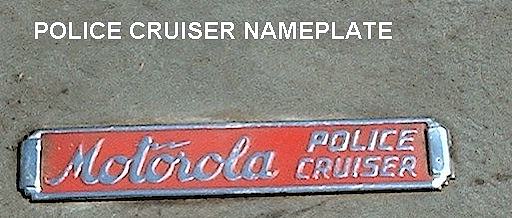
Galvin police receivers prior to WWII were called "Police Cruisers". They should have a chrome nameplate on the front of the housing which says "Police Cruiser" in script, with a red or blue painted background. The word Motorola does not otherwise appear on the exterior of the receiver itself, but is on the face of the control head in the form of a red painted metal nameplate. With the exception of the P-69-18SP-2, and the P-69-17 when mated with a transmitter, all Police Cruiser receivers were originally intended to mount on the automobile firewall, behind and below the dashboard. Again, with the exception of the "SP-1 and SP-2 versions of the P-69-18 (which uses a "DC" electrical volume control,) the volume control is located on the receiver itself and is turned via a 2 foot long "speedometer" style jacketed mechanical cable which connects to a knob on the control head. The "UHF" model P-69-17A could also be mounted in the car trunk, but with a 20 foot long speedometer type control cable running to the volume control knob under the car's dash ! A "rear" mounting option was also available, at least with the P-69-18, which consisted of a 17 foot long (!) speedometer style cable and an extension cable for the power and speaker leads.
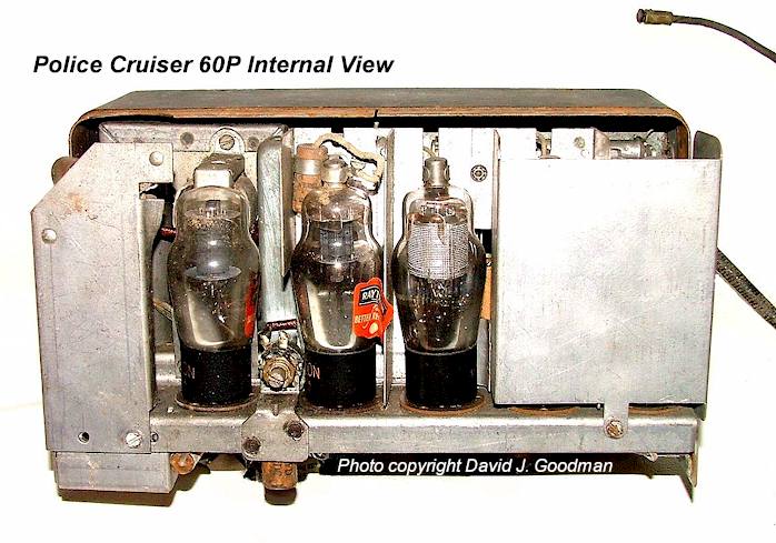
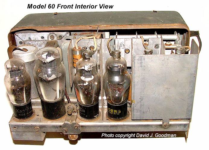
All Police Cruisers were essentially modified versions of Motorola's late 1930's AM broadcast car radios (even the "UHF" models !) and all are AM receivers. The initial offering was a slightly modified Model 60 "Golden Voice" automobile broadcast radio called Model 60P, as shown below. The basic frequency range of all Police Cruisers (except the P-69-17 and 17A) is 1500-3000 Kilocycles. The P-69-17 series covered 30-40 Megacycles. The earlier Police Cruisers generally have a black wrinkle finish, while the late-war and postwar Police Cruisers have a blue/gray wrinkle finish. The antenna input was designed for either a conventional broadcast whip or a copper "screen" antenna inside the car's headliner ("tarred fabric roof" sedans), except for the P-69-17 "UHF" receiver, which shared the transmitting "whip" antenna on the vehicle's rear quarter panel and thus required a separate T/R relay box assembly.
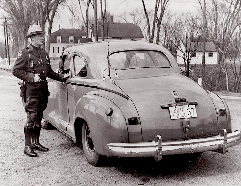
Police systems of the time broadcast on two ranges. State police, counties and highway patrol (and a few large metro areas) generally broadcast on the 1550-1750 Kilocycle band, while cities and small towns used the other band of 2300-2490 Kilocycles. In many areas, all local agencies other than state police shared the same frequency, which was often the one also used by the Highway Patrol, and thus there were small towns with systems on frequencies technically reserved for state police use. Frequencies were "coordinated" into geographic zones to minimize interference, but night-time skip conditions had become a severe problem by 1940. The Fire Radio Service was not created at the same time as the Police Radio Service and appeared some years later. At first, it was not thought necessary to have radios in fire engines! Those fire departments which did install radios, did so by licensing them as mobile police radio stations, and shared the police dispatch system.
The Models
All equipment was designed for 6 volt DC operation. There were some special production sets made for 24 and 12 Volt systems, primarily for large fire engines and trucks. Polarity was not important, although the majority of patrol cars were positive ground. All were powered by standard 4-pin auto radio vibrators. All models of P-69 Police Cruiser receivers except the P-69-14, and the very first Police Cruisers, contain two vibrators; but only one is in use at any given time. A switch which protrudes through the front panel selects the vibrator. Should one vibrator fail, the officer could reach down and select the other vibrator, allowing the vehicle to continue on patrol without the need to return to the station for radio repairs. It is a common mistake to assume the 1-2 switch on the face of the housing refers to channels, but it refers to the vibrator in use! The transmitters did not offer this feature, but the transmitter vibrators were not in use except during a transmission and were evidently considered more reliable. All P-69 Police Cruisers except the P-69-14 are crystal control, single channel. Particularly aggravating for the collector and historian is that no P-69 model numbers appear clearly or regularly on the equipment other than an apparent two digit number stamped on the lower housing shell, which was easily separated from the receiver, and on the paper tag which is glued inside the lid to show parts layout. Postwar receivers generally have ink stamped dates underneath the chassis and some of the P-69-18's contain an inked-stamped model number. The following list consists of models known to the author. There are almost certainly more.
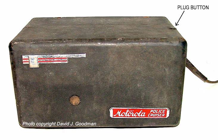
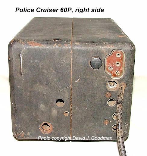
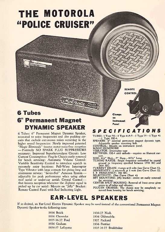
* "POLICE" and "POLICE CRUISER 60P" The first police receivers made by Galvin in late 1936-38, before the P-69 model series. Details are at best a bit sketchy on this model. Essentially a "60" model broadcast auto radio with the oscillator and RF section cut down to receive 1.5-1.7 or 2.1-2.8 Mc/s police frequencies, despite Galvin's claims to the contrary. It is unknown whether there actually was an introductory model called just "Police," although a grainy photo exists which appears to show such a set (see Harry Marnell's LAPD Radio History website,) and vibrator replacement manuals of the era refer to a separate model other than "Police Cruiser." It appears that the Model 60P was the first "Police Cruiser" branded receiver. There is anecdotal evidence that there may have been a tunable version of the 60P, however no evidence has been found. The standard 60P was crystal control. It is presumed that if there was a tunable model, it would have used the standard broadcast auto radio head but with the new frequency range marked on the dial. The original "Police" and this "Police Cruiser" required separate speakers. The case was a rectangular steel tub, the same as used by the automobile broadcast radios. Motorola has a copy of this brochure on their history pages also, but note that the date on the advertisement penciled in blue on their page is slightly incorrect - - it should be 1937, although the first Police Cruisers were indeed in production by summer 1936 (notice the car model years at the bottom, for a date reference.) All of the tubes were double-ended ST style two-digit glass types. Discontinued by 1938. Apparently no squelch control. Both Police and Police Cruiser are very rare. Motorola has a brochure for this radio on their website as a .pdf file. CLICK HERE to view the brochure.
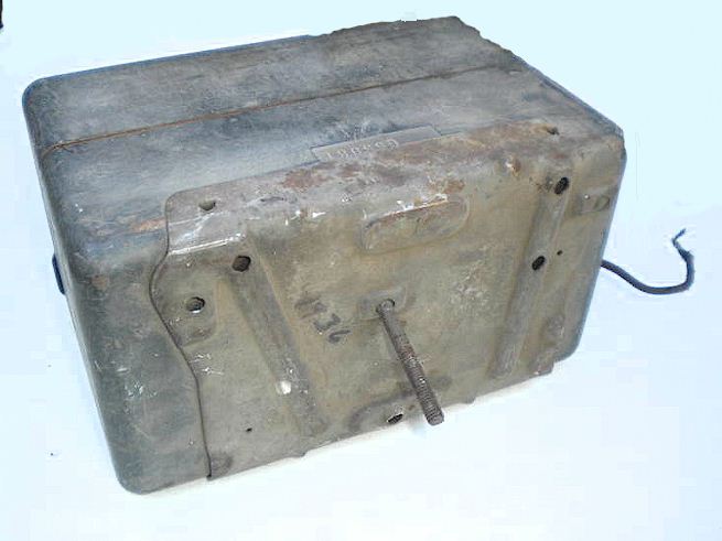
The Police Cruiser 60P should have originally been sold in a textured black color paint scheme. It's unknown whether some were shipped later in a gray wrinkle finish. The accessory speaker housing was made of molded, thick cardboard and intended to bolt to the car front headliner area above the rear view mirror. Considering how fragile they were, it is amazing that any have survived. The tub was intended to bolt through the car's firewall under the center of the dashboard.
These receivers were the first and last to offer the "Magic Eliminode" noise limiting feature, which was an application of a much earlier "spark era" technique which applied a signal from a "noise antenna" out of phase with the signal from the actual antenna, the idea being that this would cancel the noise. In the case of the Police Cruiser, the "noise antenna" was a coupling to the DC power wiring. This may be similar to the "Lamb" noise silencer popular among ham designs in the mid-1930's.
The 60P is shown below. Note that a plug button covering an access hole exists on the 60P at the upper right corner but does not on the "60" car broadcast radio.
Note the similarity to the regular car radio Model '60' shown below:
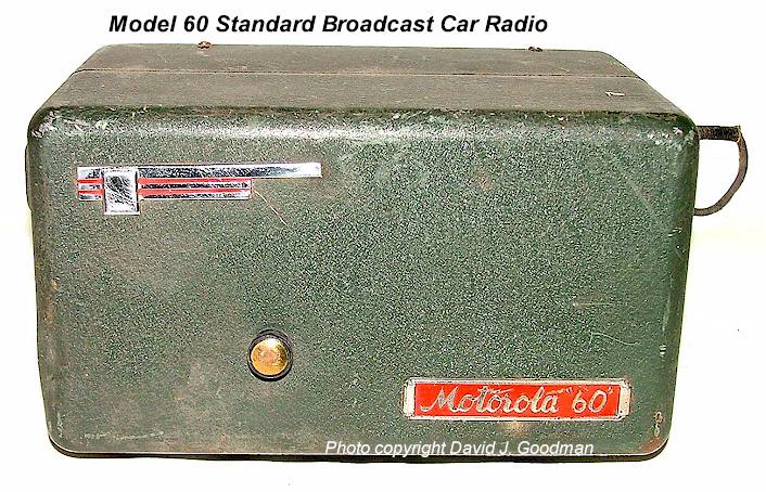
Both the Police Cruiser and Model "60" have a firewall mounting bracket as shown below.
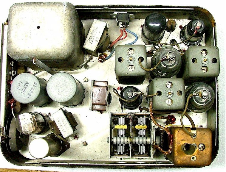
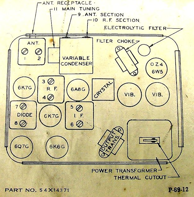
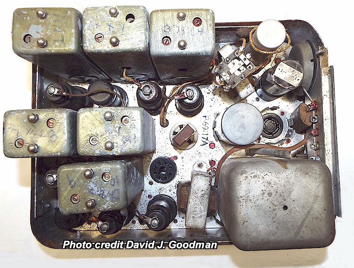
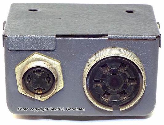
* P-69-12: 6 tube "economy model". Crystal control, single channel. Dual selectable vibrators. Uses button cell bias batteries in the audio section. Exterior black wrinkle enamel. 1550-3000 kilocycle range. Appearance quite similar to P-69-18. Production dates approximately 1939-42. Note that the nameplate is blue rather than red as on P-69-13 and P-69-18. The example in the photo below has a Cinch-Jones connector added near the audio output transformer which is not original. The hole in the case at the upper left is to allow adjustment of the antenna trimmer once the set is installed in a vehicle. Uncommon.
Photos courtesy David J. Goodman, WA8UIT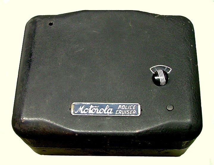
* P-69-13: 8 tube "deluxe model". Crystal control. Dual selectable vibrators. Exterior black wrinkle enamel. The most common Police Cruiser prewar model other than the P-69-12. Dual selectable vibrators. 1550-3000 kilocycle range. Appearance nearly identical to P-69-18. Production dates approximately 1939-42. Common. The squelch control was normally preset and located behind a metal plug-cap on the housing (see below.)
A rather shabby example appears below. Note that the
nameplates are missing from the front of the housing.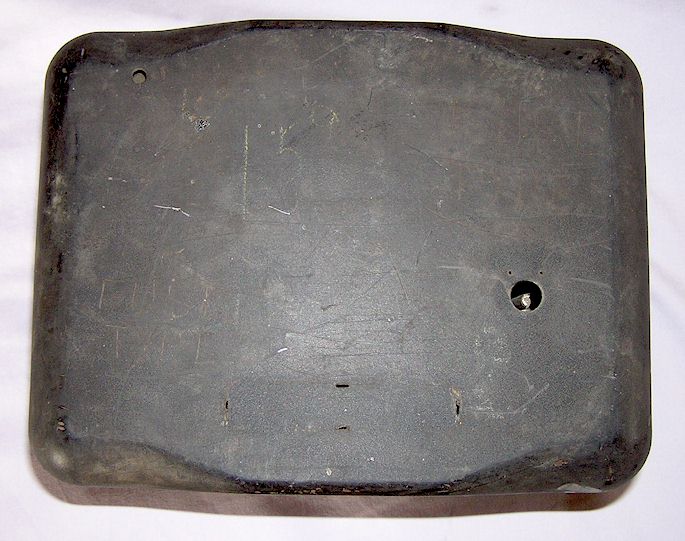
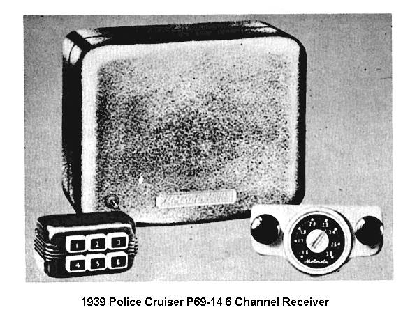
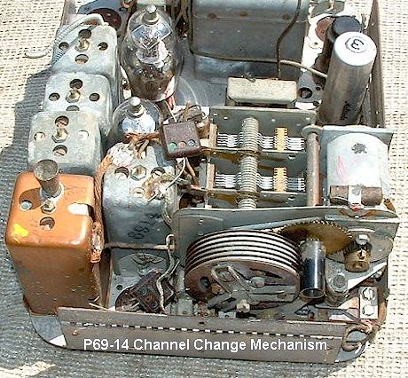
* P-69-14: 6 tube tunable non-crystal model. Used with the 6-pushbutton control box shown in photo below. Case essentially the same as other Police Cruiser models, but note the location of the "Police Cruiser" nameplate and the lack of capped tuning adjustment holes. Probably produced starting in late 1939 or early 1940.
Single vibrator. Examples seen have had gray wrinkle painted cases. Used extensively by California Highway Patrol, 1938-50. The pushbutton shown on the lower left of the radio housing is referred to as the "tone control pushbutton." There appears to have been no squelch circuit on the P69-14. There are at least two variations of case shape among P-69 -14 receivers. Rare.
Above photo courtesy Daniel Noble, Motorola Inc.
Photos below courtesy Robert Thompson
* P-69-14A through P-69-14B: No information is available on how these vary from the original P69-14, or whether there actually were P69-14A or B models, but as there was a "C" model, presumably there were. As all other P-69-14's, these were tunable, not crystal controlled.
* P69-14C: The P-69-14C featured seven single-ended octal tubes (only six tubes in the original P69-14,) included squelch, and did not feature the "tone control" of the P69-14. The apparent difference was a switch to more modern octal based tubes. Otherwise, essentially the same as the P-69-14. Probably dates from 1943-1944. Rare.
* P-69-14D: 8 tube "pushbutton" 4 channel model. Tunable, not crystal. Improved version of P-69-14C, using single ended octal based tubes. Elongated case, shape is different from the other P-69-14's. Channels still changed by electromechanical solenoid stepper system. Single vibrator. Color finish is believed to have been gray wrinkle. Control head involved separate pushbutton channel selection box. This model believed very rare. . Production dates probably 1944-47. The solenoid channel selector system was reported to have been unreliable. This model appears to have competed with a similar set manufactured by RCA, which was used by the FBI and federal agents. Rare.
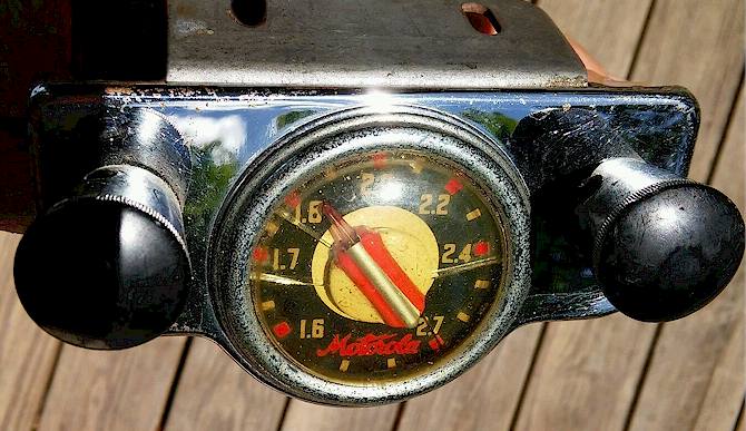
Below is a typical P69-14 control head, rather obviously a modified car radio control head. Note the frequency scale has been changed to reflect the police range.
* No P-69-11, P-69-15 or P-69-16 sets are believed to have been manufactured. It is also believed that assorted special versions were made to customer order, such as non-standard power supply inputs, mounting schemes and so forth.
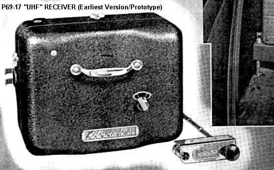
* P-69-17 (P-69-17A): 8 tube VHF AM model. Operated in the 30-40 Megacycle range, crystal control. Single channel. Exterior black wrinkle enamel. Case style in front is slightly different from others; holes for alignment points are present a large handle is mounted on the front panel (evidently it was thought this new "UHF" set would need more frequent service !) Used then-new 1853 (6AB7) VHF tube as RF amplifier. Intended as the companion to the T-69-20A VHF AM transmitter in all "UHF" 2-way systems. The Motorola P-374-A control head physical appearance is unknown; it is similar to other Cruiser heads but has a squelch on/off switch and mechanical volume control knob. The P-69-17A is essentially the same as the P-69-17 other than a redesigned squelch circuit. The P-69-17 was often trunk-mounted, in contrast to medium wave receivers, and shared the transmitting antenna via a T/R relay. Production dates approximately 1941-49. Somewhat rare. These were used primarily by small cities which did not need long range or inter-operability with state and county systems. The P-69-17 is not particularly sensitive and with the low power of the companion T69-20A transmitter, range would have been somewhat less than that of a modern CB radio. Common.
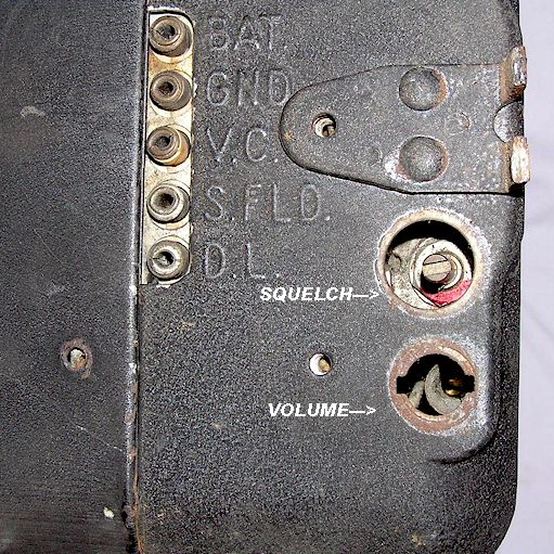
The photo below shows an early P-69-17 with the same control head as the other Police Cruisers which were crystal controlled. The head for the P-69-17A added a toggle switch for squelch between the pilot lamp and the volume control.
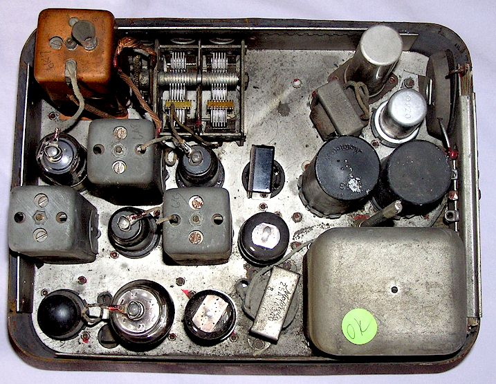
Interior view of P-69-17A below. The relay in the upper right corner has been added by someone for purposes unknown, probably a receiver muting relay for use with a transmitter.
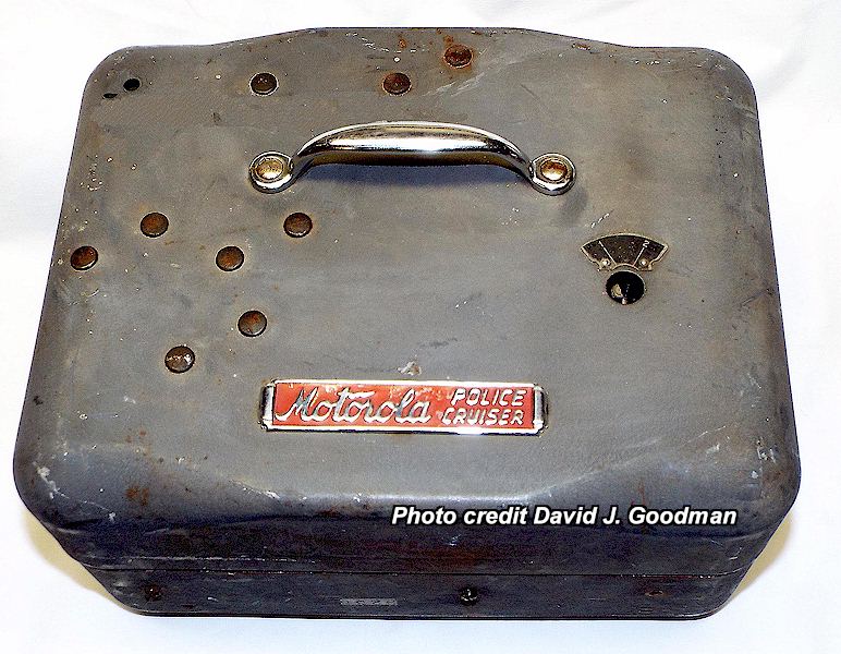
* P-69-18: 8 Tube Medium wave receiver, the final and last generation Police Cruiser. 1941 is believed to be introduction date. Crystal control, dual vibrators. These were shipped in a black wrinkle color scheme until sometime after 1945, when the color was switched to gray wrinkle. Control head same as P-69-13 series. Circuitry almost identical to P-69-13 series, except for slight electrical improvements. Produced at least through 1949. The knobs are the same as shown on the P-69-12 above. Somewhat common. The squelch control was moved to the front panel and provided with a knob, unlike previous versions, where it was located behind a plug button on the side of the housing, as shown on the P-69-13 above.
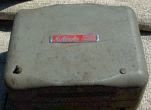
Shown below is an unusual, apparently early P-69-18 with a blue nameplate and a handle on the upper cover. This cover is friction-fit only, there are no screws securing it as on other models. Also interesting is that it has ventilation holes in the cover, while others do not (see photo below it.)
Photos courtesy David J.
Goodman, WA8UIT 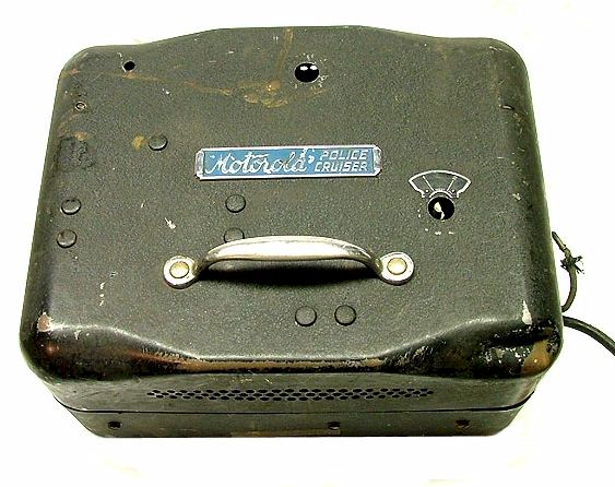
Interior view:
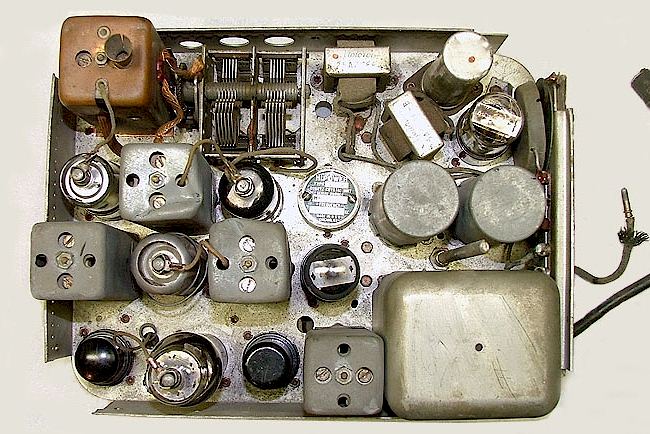
The photo below shows a typical early P-69-18 with a black housing and a red nameplate.
P-69-18 SP1, Photo courtesy David J. Goodman, WA8UIT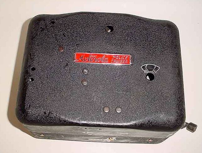
CLICK HERE FOR SOME AMAZING PHOTOS OF A BRAND NEW P-69-18 FOUND IN AN ESTATE!
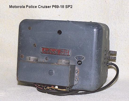
* P-69-18 SP-1 and SP-2: Probably 1941 or later-dated modified P-69-18. Crystal control, single channel. Selectable dual vibrators. Exterior blue-gray wrinkle enamel on SP2. Both of these modifications remote-wired the volume control so that it would be controlled at a separate control head, electrically, and were mainly intended to allow mounting the Police Cruiser in the vehicle trunk. Also included in the SP-1 manual is an instruction on how to wire the squelch to also be controlled by the remote head, the factory squelch control on the chassis then being unused. The SP-2 is already wired this way and was mainly intended to facilitate the addition of a transmitter to the mobile installation and placement of the receiver in the vehicle trunk compartment.
The new volume control was then a DC remotely controlled design rather than the speedometer style cable of earlier models. Otherwise, the set is the same as the standard P-69-18. The control head is the P-8022 as used on wartime and postwar Deluxe Line FM sets. The -SP2 modification includes the -SP1 modification, but also allows trunk mounting of P-69-18 by adding a cable connector box (see photo below) which allows the receiver to interchange with a Deluxe Line FMR-13V VHF FM receiver and be compatible with an FMTR-30D radio accessory set. The -SP1 modification used a small round connector on a short pigtail lead to electrically remote the volume and squelch controls. The -SP2 used pin-tip plugs which attach to the cable connector adapter box. Production dates were approximately 1944-50. It is believed that most were produced in the 1945-49 era. The SP-2 shown below was used by the California Highway Patrol until 1950, trunk mounted with both Motorola FMT-30D and FMT-25V transmitters, as well as RCA FM transmitters (the RCA interconnections being made in-house by CHP's radio technicians.)
RECEIVER CONTROL HEADS:
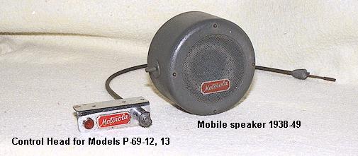
Shown below are the standard speedometer cable style "remote" control head for the P-69- series Police Cruiser receivers which did not feature electrical volume control, namely the P-69-12, 13 and 18, and the "small" mobile speaker. There was also a "large" mobile speaker, featured in the photo of the transmitter installation shown later on this page. Squelch was adjusted at the receiver chassis itself and not accessible by the operator.
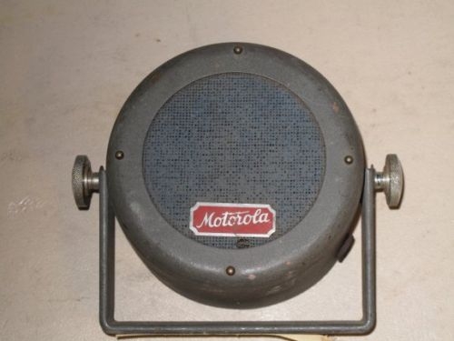
Typical trunnion mount speaker:
MOBILE TRANSMITTERS:
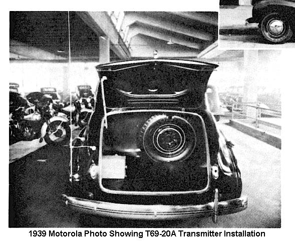
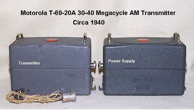
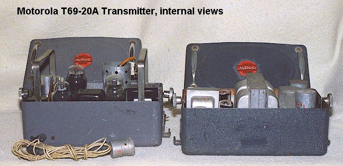
The first Motorola AM mobile transmitter was the T-69-20A. If there was a non-"A" model, it must have been a prototype. This appears to have been Motorola's only AM mobile transmitter, and is a two piece set in which the power supply and modulator are in one case and the RF section in a second. As originally configured, the power supply was usually installed on the firewall of the automobile, next to the receiver and under the glove box, while the RF section was located in the trunk and attached to its antenna via a short braided copper rope. A rather thick cable delivered the high voltage and other lines back to the trunk, under the floor mat. However, placing both sections in the vehicle trunk was a popular option.
This transmitter operates in the 30-40 Megacycle range, using an 807 power amplifier tube modulated by a 6N7. It is crystal controlled on a single frequency and outputs approximately 10 Watts. The power supply is a 6 volt type.
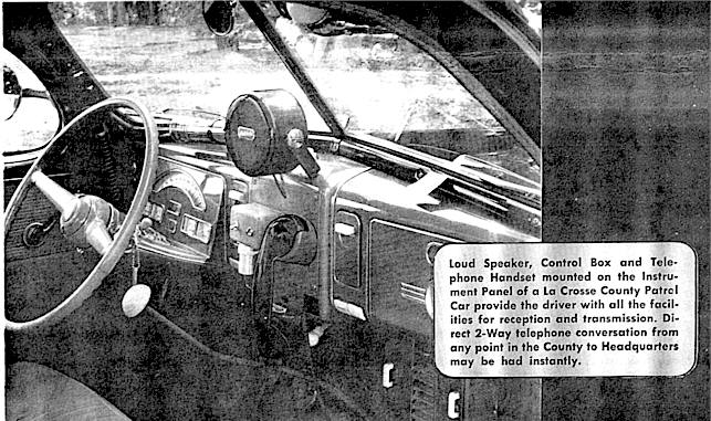
Exterior color of the units is blue-gray wrinkle enamel, with color shades varying substantially over the years of production, as the photos below show. The T-69-20A was introduced in August, 1939. Production continued through approximately late 1949. The control head was available as a "handset" type, in which a push to talk Western Electric "E" series telephone handset hung alongside or on a cradle on top of the control head, which was a gray square box with Amphenol connectors on the bottom for the control cable connections. Later versions featured a Western Electric "F" series handset, as shown below. A microphone type control box was alternately available; this is believed to have been the same control box, simply missing the handset cradle. The control head only controlled the transmitter; the receiver retained its own control head . There were at least two variations of T-69-20A control head style. See typical T69-20A installation photo below. Typically supplied by 1942 was the standard under-dash P-254 head as also shown below, which was normally used with a microphone.
Standard P-254 Control Head
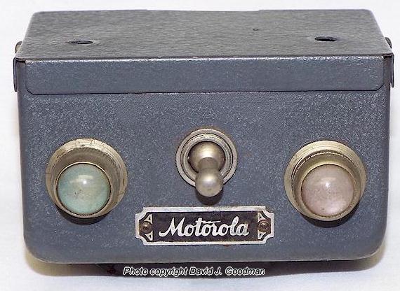
This was the standard control head for the T-69-20A although there were at least two other styles which were earlier, such as the one shown in the photo above, which has the connector on the bottom apron, and another, upon which the cradle for a Western Electric "E" style handset was hung.
"SPECIALS":
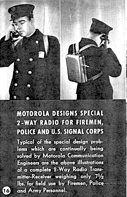
Various special production radios were produced. One such example is the curious pack-set transmitter-receiver appearing below, which is shown in a circa 1941 Motorola catalog. It is believed this unit was essentially a prototype which led to the postwar FPTR-1 and FHTR-1 series pack sets. Probably few (if any ?) were actually sold.
"ONE PIECE SETS":
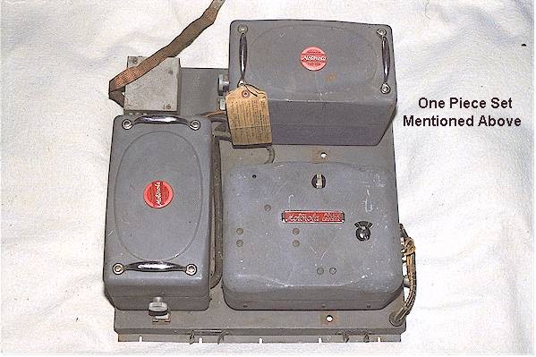
During wartime and to the end of Police Cruiser production, a kind of "one-piece" two-way radio set was manufactured, which consisted of both T-69-20A transmitter cases and a P-69-18 or -17 Police Cruiser receiver, all mounted on a large copper plated chassis, which was mounted in the trunk compartment of a police car or in a utility compartment on a fire engine. This was the Model TR 20-17 if equipped with the P69-17 receiver or the TR 20-18 if using the P69-18 medium wave set. It appears there was also a TR 20-13, an earlier model using the P69-13 receiver. The later versions of these sets used the P-8022 control head for both receiver and transmitter functions while earlier used the separate heads of each component. They were purchased by the US Government in some quantity and popular in fire engines, whuich at the time had to be licensed as police mobiles and use their frequency as there was no fire radio service until after WWII. . For example, they were used in the trunks of Signal Corps staff cars for the 1940 annual War Games at Camp McCoy, Sparta, Wisconsin (believed to be P-69-17A / T-69-20A combinations, (in a TR 20-17 setup.) Advertisements in CQ Magazine in the late 1940's by surplus dealers offered these as having come from "military police service." There were several varieties of steel platforms used to mount these "one piece" sets. One platform only mounted a T-69-20A transmitter and its power supply in the trunk, without a receiver (which was still dash mounted, thus not really a "one piece" set.) The original platforms often contained legs to allow them to be suspended in the auto trunk, next to or above the spare tire. Few (or no?) platforms have survived.
The one piece TR 20-18 set shown here was used by the Tracy, California Fire Department in a fire engine and was licensed as a police transmitter, into the late 1940's. It contains a P-69-18 receiver and a T-69-20A transmitter. For some reason the orientation of the receiver seems to have been altered. The square box on the upper left corner is a transmit-receive relay to allow use of a single antenna.
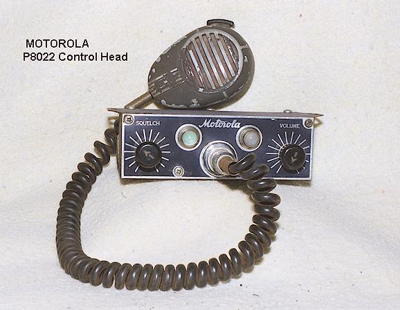
The P-8022 control head above was often used with the "one piece" installation shown above it, but not with the original T-69-20A installations, which used separate control heads for transmitter and receiver. This control head was primarily used with the "Deluxe" line of FM equipment, introduced in late 1940. Also note that coiled microphone cords are a postwar development. The original microphone used with the above control head would have had a straight cord, and would have had a more flush-appearing, "push up to talk" button which identified the earliest Shure Mfg. Corp. mobile microphones used by Motorola. In addition, the rear "hang-up button" was a wartime development. Prewar mikes would have had a hang-up ring on the top instead. the microphone above is a standard Shure postwar CB-12 model found with the control head as shown. As an aside, the above control head, last produced in approximately 1949, was still in use by the Los Angeles Police Department even in1960, and possibly beyond, operating a custom made mobile radio with a low frequency AM receiver and a VHF transmitter. LAPD did not abandon low frequency dispatch until 1965.
NOTE REGARDING CAR-TO-CAR OPERATION: Readers may wonder how radio equipped cars communicated with each other directly using medium frequency receivers and VHF AM transmitters. Normally, they couldn't! However, there was an interconnect function available at the base station, which allowed the audio from the base station receiver to be fed into the microphone line of the base station transmitter, and the base station would be left on the air continuously as long as this switch was closed. This function, often called the "hot button," allowed cars to communicate with each other in emergencies, such as coordinating chases and so forth. Of course, mobile units with microphones instead of handsets, and with separate antennas, would need to reduce the receiver volume to prevent feedback, as such a system was "full duplex."
MIX AND MATCH:
It was not uncommon to find Motorola receivers or transmitters matched up with competitive makes of equipment. This was particularly true during the war years when it was difficult to source equipment and limited money to do so. For example, some agencies might have started out with Philco mobile police receivers, and then added Motorola T-69-20A transmitters. Or, a Galvin Police Cruiser receiver installation might have had a Stancor or GE transmitter added later. Some of the earliest postwar 2-way California Highway Patrol installations started out with a Police Cruiser receiver, and added both Motorola and RCA 39 Megacycle VHF FM transmitters later, in the case of the RCA by modifying the RCA control head to operate the P-69-18 Motorola receiver !
THE ANTENNAS:
In Police Cruiser receive only installations (1 way radio), the antenna used was a regular broadcast whip. Typically recommended was the Motorola "Super Cowl" antenna as shown in the Motorola brochure for the first generation Police Cruiser set mentioned in the link to the Motorola archives page above. Other options included the "screen" antenna and an extra length "super" broadcast whip. The "screen" antenna was only used in cars of the 1920's and early 1930's, which still had a roof made of a tarred fabric material rather than a full steel roof. A copper or bronze screen was inserted between the "tar" top and the wooden slats of the roof, and the lead-in brought down to the receiver through the hollow post on one side of the windshield. The "screen" antenna was far superior to all other types, but disappeared into history when cars began being manufactured with all metal roofs (called "turret top" cars.) . There were other antenna designs, which were unsuccessful, such as a trombone shaped affair which mounted under the auto running board on the driver's side, on insulated spacers, or the front bumper being used as an antenna by completely rubber-insulating it from the rest of the auto chassis. Although outside the scope of this web page, motorcycles did make use of the screen antenna to some extent. Old photos show the screen, about the size of a ping-pong paddle, mounted horizontally on insulators above the rear fender.
In two-way installations, a separate antenna was used for the transmitter. Motorola's original antenna was a strange three-legged tripod affair as shown below and in the above photograph of a T-69-20A in a police car, and featured an adjustable length whip. The one-piece set shown above included a transmit-receive antenna relay, in a small box, such that the only antenna necessary would be the transmitting antenna on the rear of the patrol car, as in modern installations. This had the disadvantage that in cases where the receiver was a low frequency type, full duplex operation was no longer possible.
WARTIME AND POSTWAR FM EQUIPMENT:
FM began to be used extensively in 1940. GE had sold and installed a small VHF FM system for a sheriff's department early in the year. The first large system to use FM was the Connecticut State Police radio system, in operation by summer 1940, with equipment built and designed by Fred M. Link Radio Co. under supervision of Professor Daniel Noble, consultant. Noble had observed the GE FM equipment but didn't like it, instead picking Link to manufacture equipment to his specifications. Noble would almost immediately thereafter join Galvin (Motorola) in direct competition with Link. It can be seen that it was no accident that the Motorola FM equipment bore a close resemblance to the Link designs ! By late 1940, Galvin (Motorola) had announced its own line of FM equipment, and the other manufacturers quickly followed.
FM was not an immediate success, and initially few units were sold. The war emergency on December 7, 1941 curtailed most civilian production. Link was able to sell quantities of his VHF FM police equipment based on the Connecticut designs to the military for use in armored vehicles being shipped to North Africa. Motorola also won a number of military contracts with their new FM equipment, which would later be given the AN/VRC-2 nomenclature. During the war the development of FM police equipment continued, with some systems such as the Miami, Florida Police and the California Highway Patrol operating 118 Megacycle FM systems (Miami for mobile radios, CHP for mountaintop relays.) The California Highway Patrol began using Motorola FM transmitters in its patrol cars in 1941 on an experimental basis, and during the war would buy hundreds of them. The widespread success of VHF FM in armored units during the war proved its superiority in mobile operation, and the men who would return from war to work in and design mobile radio systems had learned its advantages. There was widespread conversion to FM and "UHF" at the end of the War, when the FCC made permanent allocations of 30-40 and 150-174 Megacycle range frequencies to police and emergency radio systems and reassigned the 118 Megacycle band to aircraft use. The FCC also issued an order at the end of the war that all new police radio systems were to be on the new 150 Megacycle band, absent a showing of need to remain on the 30-50 Megacycle band.
Motorola's FM equipment was called the "Deluxe" line, although they appear to have thought up that name sometime after the equipment was first marketed. The Deluxe line was a superb piece of equipment for its day, reliable and offering high performance. It outperformed the AM equipment to a significant degree in both range and clarity, and represented Motorola's primary product line after the War. Once production of the FM equipment was in progress, Motorola ceased promotion of AM equipment altogether although it was still being produced and available for purchase for another ten years. Shown below is the first Deluxe line equipment to be offered; typical model numbers would have been the FMR-13(V) 30-40 Megacycle FM receiver on the right, the FMT-30(D) 25 Watt 30-40 Megacycle FM transmitter on the left, and the P-8022 standard control head in front. The Deluxe line went through a number of improvements, which will be detailed in a separate web page covering Motorola postwar and 1950's equipment.
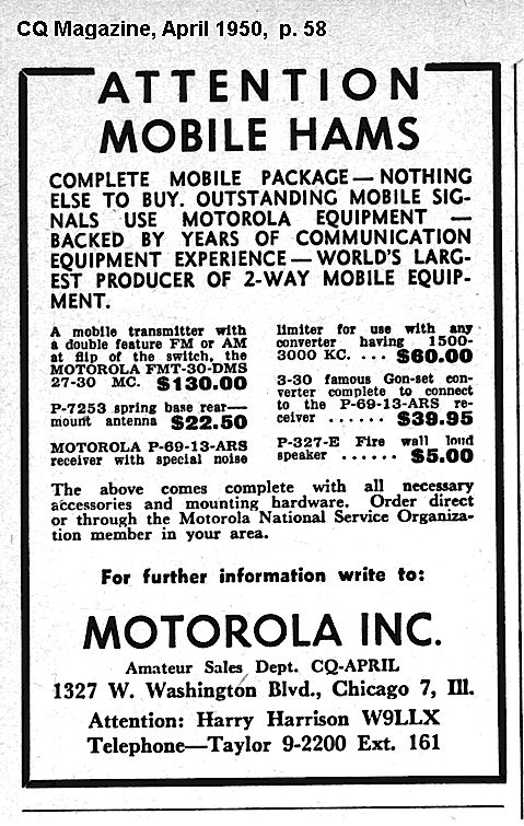
Below is an interesting advertisement from Motorola offering equipment to radio amateurs, presumably refurbished although not so stated:
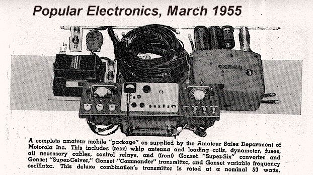
By 1955 the Police Cruisers were still being sold to amateurs, only this time with newer Gonset accessories and a Gonset Commander transmitter:
CURRENT VALUES:
I frequently get questions as to what a Police Cruiser receiver or T-69-20A transmitter is worth, usually from folks intending to sell found items on Craigslist. The only accurate answer is "Whatever someone else is willing to pay for it." That being said, friends and I regularly buy used "as found" Police Cruiser receivers on eBay in the $ 15-35 range depending upon condition. Less, at flea markets and estate sales. T-69-20 transmitters, approximately the same amounts. Slightly higher if the control heads, speakers or any cables are included. It should be noted that tens of thousands of these sets were manufactured during a thirteen year period, there is no collector following for this equipment, and it is not sought after. Therefore do not expect a windfall if you find one of these!
This page is maintained and updated by Geoff Fors, WB6NVH, in Monterey California USA. It is intended to convey historical information rather than be a masterpiece of web design ! It is a private effort not sponsored by Motorola.
If you have or are looking for old police radio information, printed materials, equipment, parts, photos, etc. let me know! Any submissions can be added to this and other web pages I am creating. You can contact me via e-mail by manually entering my address as geoff @wb6nvh.com. By regular mail: Geoff Fors, PO Box 342, Monterey California 93942. If you are interested in old land mobile technology, contact me! I am always looking for others to share resources, equipment and knowledge. I am looking for other examples of old police radio equipment from the 1930's and 1940's - - don't let this equipment wind up at the landfill!
Thanks to Ray Grimes of Motorola, Inc. for some of the black & white brochure photos
Check out my other web pages, click on any of these:
Main California Highway Patrol Radio History Pages
Current California Highway Patrol Radio Systems
Regency M100 Scanner Conversion
Russian Lavina M HF Portable Transceiver
Regency RH256 Mobile Radio Programming Instructions
GE / Ericsson S825 Control Head Programming Tutorial
Ver. 2/16/2022 © 2000 All Rights Reserved